
2009


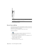
Table Of Contents
- Contents
- Tubes and Pipes
- 1 Getting Started with Tube & Pipe
- 2 Route Basics
- 3 Setting Styles
- 4 Creating Rigid Routes and Runs
- General Workflow for Rigid Routes
- Creating Auto Route Regions
- Manually Creating Parametric Regions
- Automatically Dimension Route Sketches
- Create Segments With Precise Values
- Define Parallel and Perpendicular Segments
- Snap Route Points to Existing Geometry
- Place Constraints On Route Sketches
- Create Bends Between Existing Pipe Segments
- Create Pipe Routes With Custom Bends
- Create Bent Tube Routes
- Realign 3D Orthogonal Route Tool
- Control Dimension Visibility
- Populated Routes
- 5 Creating and Editing Flexible Hose Routes
- 6 Editing Rigid Routes and Runs
- 7 Using Content Center Libraries
- 8 Authoring and Publishing
- 9 Documenting Routes and Runs
- Cable and Harness
- 10 Getting Started with Cable and Harness
- 11 Working With Harness Assemblies
- 12 Using the Cable and Harness Library
- 13 Working with Wires and Cables
- About Wires and Cables
- Setting Modeling and Curvature Behavior
- Inserting Wires and Cables Manually
- Moving Wires and Cables
- Deleting Wires and Cables
- Replacing Wires
- Assigning Virtual Parts
- Importing Harness Data
- Adding Shape to Wires and Cable Wires
- Setting Occurrence Properties
- Changing Wire and Cable Displays
- 14 Working with Segments
- 15 Routing Wires and Cables
- 16 Working with Splices
- 17 Working with Ribbon Cables
- 18 Generating Reports
- 19 Working Nailboards and Drawings
- IDF Translator
- Index

NOTE The results in your exercise may differ from figures illustrated in this chapter,
depending on specific working environment, original assembly, and workflow
used.
Using Drawing Templates
When documenting a tube and pipe assembly, each new drawing file uses a
drawing template. You can update existing templates or create and add new
ones into the Templates folder. For Windows
®
XP this located under Program
Files\Autodesk\Inventor<version>\Design Data\Tube & Pipe by default. For
Windows
™
Vista this located under
Users|Public\Documents\Autodesk\Inventor<version>\Design Data\Tube & Pipe
by default.
For more information about customizing drawing templates, refer to Autodesk
Inventor Help and go to templates, annotate tube and pipe drawings in the
index.
Preparing Design View Representations
A Design View is created in the assembly environment and preserves a
designated representation view of assembly components. It can be mapped
to drawing views of the assembly file.
In cases where only specific pipe runs in a complicated assembly need to be
documented, you can define a specific design view in which components that
are contained in the top-level assembly but not within the pipe runs are
hidden. Thus, components with Visibility off are not displayed in the drawing
view when the relevant design view is selected for the drawing file.
Before creating drawing views for pipe runs, you can customize specific design
views for the assembly environment using the Design View Representations
tool.
In this exercise, you create a design view in which you turn off the visibility
of IBeam in the tube and pipe assembly, AirSystemAssy.iam.
Create a new design view
1 Open the AirSystemAssy.iam assembly.
Using Drawing Templates | 183