
2009


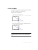


Table Of Contents
- Contents
- Tubes and Pipes
- 1 Getting Started with Tube & Pipe
- 2 Route Basics
- 3 Setting Styles
- 4 Creating Rigid Routes and Runs
- General Workflow for Rigid Routes
- Creating Auto Route Regions
- Manually Creating Parametric Regions
- Automatically Dimension Route Sketches
- Create Segments With Precise Values
- Define Parallel and Perpendicular Segments
- Snap Route Points to Existing Geometry
- Place Constraints On Route Sketches
- Create Bends Between Existing Pipe Segments
- Create Pipe Routes With Custom Bends
- Create Bent Tube Routes
- Realign 3D Orthogonal Route Tool
- Control Dimension Visibility
- Populated Routes
- 5 Creating and Editing Flexible Hose Routes
- 6 Editing Rigid Routes and Runs
- 7 Using Content Center Libraries
- 8 Authoring and Publishing
- 9 Documenting Routes and Runs
- Cable and Harness
- 10 Getting Started with Cable and Harness
- 11 Working With Harness Assemblies
- 12 Using the Cable and Harness Library
- 13 Working with Wires and Cables
- About Wires and Cables
- Setting Modeling and Curvature Behavior
- Inserting Wires and Cables Manually
- Moving Wires and Cables
- Deleting Wires and Cables
- Replacing Wires
- Assigning Virtual Parts
- Importing Harness Data
- Adding Shape to Wires and Cable Wires
- Setting Occurrence Properties
- Changing Wire and Cable Displays
- 14 Working with Segments
- 15 Routing Wires and Cables
- 16 Working with Splices
- 17 Working with Ribbon Cables
- 18 Generating Reports
- 19 Working Nailboards and Drawings
- IDF Translator
- Index

■ User Defined: A positive number moves the free
fitting or component away from the connected base
fitting or component. A negative number moves
the free fitting or component toward the connected
base fitting or component.
Indicates the engagement distance used for the connec-
tion between fittings and components. Read-write only
when the User Defined engagement type is used.
Distance
In this exercise, you connect the hose route to the upper tee you manually
placed. The hose route is flexible and acts as the free fitting.
Connect fittings and components
1 Activate the AirSystem1:1 run.
2 Expand the Flexible Hose 02 assembly, and then activate the hose route.
3 In the graphics window, right-click the intermediate Route Point 2, and
select Delete.
The hose route recalculates the hose length.
4 Right-click and select Finish Edit.
The AirSystem1:1 run is activated.
5
On the Tube & Pipe panel bar, click the Connect Fittings tool.
6
On the Connect Fittings dialog box, ensure the Connect Fittings
tool is enabled.
7 Ensure the Free Fitting tool is selected and click the hose fitting.
8 Click the Base Fitting tool, and then click the tee fitting on the upper
segment.
140 | Chapter 6 Editing Rigid Routes and Runs