
2009

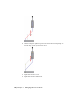


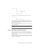


Table Of Contents
- Contents
- Tubes and Pipes
- 1 Getting Started with Tube & Pipe
- 2 Route Basics
- 3 Setting Styles
- 4 Creating Rigid Routes and Runs
- General Workflow for Rigid Routes
- Creating Auto Route Regions
- Manually Creating Parametric Regions
- Automatically Dimension Route Sketches
- Create Segments With Precise Values
- Define Parallel and Perpendicular Segments
- Snap Route Points to Existing Geometry
- Place Constraints On Route Sketches
- Create Bends Between Existing Pipe Segments
- Create Pipe Routes With Custom Bends
- Create Bent Tube Routes
- Realign 3D Orthogonal Route Tool
- Control Dimension Visibility
- Populated Routes
- 5 Creating and Editing Flexible Hose Routes
- 6 Editing Rigid Routes and Runs
- 7 Using Content Center Libraries
- 8 Authoring and Publishing
- 9 Documenting Routes and Runs
- Cable and Harness
- 10 Getting Started with Cable and Harness
- 11 Working With Harness Assemblies
- 12 Using the Cable and Harness Library
- 13 Working with Wires and Cables
- About Wires and Cables
- Setting Modeling and Curvature Behavior
- Inserting Wires and Cables Manually
- Moving Wires and Cables
- Deleting Wires and Cables
- Replacing Wires
- Assigning Virtual Parts
- Importing Harness Data
- Adding Shape to Wires and Cable Wires
- Setting Occurrence Properties
- Changing Wire and Cable Displays
- 14 Working with Segments
- 15 Routing Wires and Cables
- 16 Working with Splices
- 17 Working with Ribbon Cables
- 18 Generating Reports
- 19 Working Nailboards and Drawings
- IDF Translator
- Index

It is enclosed in parentheses as displayed in the
graphics window and allows route geometry to dynam-
Driven dimension
ically respond to associated changes. It typically occurs
on the route sketch that relates to the assembly geom-
etry or when an auto region is converted to a paramet-
ric region.
You can switch between the driven dimension and the normal sketched
dimension using the Drive Dimension tool on the standard toolbar. Once a
driven dimension is switched to a normal sketched dimension, you can edit
the value. If converting the driven dimension to a driving dimension will
over-constrain the geometry, the conversion is not allowed.
Driven Dimension tool
In the route environment, normal sketched dimensions can be manually set
using the General Dimension or edits in place. If you want to place dimensions
based on geometry outside of the active route, you must first include it in the
route sketch using the Include Geometry tool.
General Dimension tool
NOTE Placing dimensions may over-constrain the route sketch. You may also fail
to switch the dimension type. You can identify the geometric constraints as needed.
In this exercise, you edit the segment length in place. For more information
about how to place and edit dimensions on the route sketch (3D sketch), refer
to Autodesk Inventor Tube & Pipe Help and Autodesk Inventor Help.
Edit the route dimension
1 Activate Route03 in the AirSystem1:1 run.
2 Double-click the dimension on the last segment as shown in the following
image.
Dimensions | 127