
2009


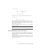


Table Of Contents
- Contents
- Tubes and Pipes
- 1 Getting Started with Tube & Pipe
- 2 Route Basics
- 3 Setting Styles
- 4 Creating Rigid Routes and Runs
- General Workflow for Rigid Routes
- Creating Auto Route Regions
- Manually Creating Parametric Regions
- Automatically Dimension Route Sketches
- Create Segments With Precise Values
- Define Parallel and Perpendicular Segments
- Snap Route Points to Existing Geometry
- Place Constraints On Route Sketches
- Create Bends Between Existing Pipe Segments
- Create Pipe Routes With Custom Bends
- Create Bent Tube Routes
- Realign 3D Orthogonal Route Tool
- Control Dimension Visibility
- Populated Routes
- 5 Creating and Editing Flexible Hose Routes
- 6 Editing Rigid Routes and Runs
- 7 Using Content Center Libraries
- 8 Authoring and Publishing
- 9 Documenting Routes and Runs
- Cable and Harness
- 10 Getting Started with Cable and Harness
- 11 Working With Harness Assemblies
- 12 Using the Cable and Harness Library
- 13 Working with Wires and Cables
- About Wires and Cables
- Setting Modeling and Curvature Behavior
- Inserting Wires and Cables Manually
- Moving Wires and Cables
- Deleting Wires and Cables
- Replacing Wires
- Assigning Virtual Parts
- Importing Harness Data
- Adding Shape to Wires and Cable Wires
- Setting Occurrence Properties
- Changing Wire and Cable Displays
- 14 Working with Segments
- 15 Routing Wires and Cables
- 16 Working with Splices
- 17 Working with Ribbon Cables
- 18 Generating Reports
- 19 Working Nailboards and Drawings
- IDF Translator
- Index

6 In the Model browser, verify that the Autoroute1 node disappears.
7 Right-click and select Finish Edit.
Dimensions
Auto regions always dynamically update to assembly changes and the shape
of the route may vary from the original auto route solution. They do not
involve dimensions until you convert them to parametric regions.
For parametric regions, there are three typical types of dimensions pertaining
to the route sketch:
■ Linear dimension, such as the segment length.
■ Radial dimension, such as the bend radius.
■ Angular dimension, such as the included angle at the direction turn.
Similar to Autodesk Inventor, dimensions on the route sketch can be
categorized into two types:
It is used to drive the route geometry. For instance,
sketched route segments are manually created using a
specified normal sketched dimension.
Normal sketched di-
mension (driving di-
mension)
126 | Chapter 6 Editing Rigid Routes and Runs