
2009

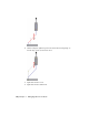


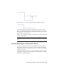
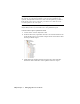


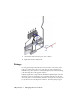
Table Of Contents
- Contents
- Tubes and Pipes
- 1 Getting Started with Tube & Pipe
- 2 Route Basics
- 3 Setting Styles
- 4 Creating Rigid Routes and Runs
- General Workflow for Rigid Routes
- Creating Auto Route Regions
- Manually Creating Parametric Regions
- Automatically Dimension Route Sketches
- Create Segments With Precise Values
- Define Parallel and Perpendicular Segments
- Snap Route Points to Existing Geometry
- Place Constraints On Route Sketches
- Create Bends Between Existing Pipe Segments
- Create Pipe Routes With Custom Bends
- Create Bent Tube Routes
- Realign 3D Orthogonal Route Tool
- Control Dimension Visibility
- Populated Routes
- 5 Creating and Editing Flexible Hose Routes
- 6 Editing Rigid Routes and Runs
- 7 Using Content Center Libraries
- 8 Authoring and Publishing
- 9 Documenting Routes and Runs
- Cable and Harness
- 10 Getting Started with Cable and Harness
- 11 Working With Harness Assemblies
- 12 Using the Cable and Harness Library
- 13 Working with Wires and Cables
- About Wires and Cables
- Setting Modeling and Curvature Behavior
- Inserting Wires and Cables Manually
- Moving Wires and Cables
- Deleting Wires and Cables
- Replacing Wires
- Assigning Virtual Parts
- Importing Harness Data
- Adding Shape to Wires and Cable Wires
- Setting Occurrence Properties
- Changing Wire and Cable Displays
- 14 Working with Segments
- 15 Routing Wires and Cables
- 16 Working with Splices
- 17 Working with Ribbon Cables
- 18 Generating Reports
- 19 Working Nailboards and Drawings
- IDF Translator
- Index

Release the cursor to stop the drag. The unwanted segment is removed.
You can then delete the extra route points using Delete from the context
menu, or by dragging the unwanted route points until they are coincident
with an adjacent one. When they are coincident, release the cursor to end the
drag and remove the route point.
While you are dragging the segment, use the ESC key to cancel the drag and
return to regular editing.
NOTE Ensure that the segment being moved does not attempt to overlap any
other existing segment. Otherwise, the system will automatically calculate a route
shape.
Convert Auto Region to Parametric Sketch
If you need to have more control over the segments in an auto region, use
the Convert to Sketch tool to convert it to a series of continuous sketched
segments. The Model browser reflects the deletion of the auto region and new
sketched route points.
All client constraints in the auto region are then deleted so more edit options
are available to adjust the route. It is equivalent to deleting all client constraints
within the auto region manually.
Convert Auto Region to Parametric Sketch | 123