
2009


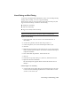


Table Of Contents
- Contents
- Tubes and Pipes
- 1 Getting Started with Tube & Pipe
- 2 Route Basics
- 3 Setting Styles
- 4 Creating Rigid Routes and Runs
- General Workflow for Rigid Routes
- Creating Auto Route Regions
- Manually Creating Parametric Regions
- Automatically Dimension Route Sketches
- Create Segments With Precise Values
- Define Parallel and Perpendicular Segments
- Snap Route Points to Existing Geometry
- Place Constraints On Route Sketches
- Create Bends Between Existing Pipe Segments
- Create Pipe Routes With Custom Bends
- Create Bent Tube Routes
- Realign 3D Orthogonal Route Tool
- Control Dimension Visibility
- Populated Routes
- 5 Creating and Editing Flexible Hose Routes
- 6 Editing Rigid Routes and Runs
- 7 Using Content Center Libraries
- 8 Authoring and Publishing
- 9 Documenting Routes and Runs
- Cable and Harness
- 10 Getting Started with Cable and Harness
- 11 Working With Harness Assemblies
- 12 Using the Cable and Harness Library
- 13 Working with Wires and Cables
- About Wires and Cables
- Setting Modeling and Curvature Behavior
- Inserting Wires and Cables Manually
- Moving Wires and Cables
- Deleting Wires and Cables
- Replacing Wires
- Assigning Virtual Parts
- Importing Harness Data
- Adding Shape to Wires and Cable Wires
- Setting Occurrence Properties
- Changing Wire and Cable Displays
- 14 Working with Segments
- 15 Routing Wires and Cables
- 16 Working with Splices
- 17 Working with Ribbon Cables
- 18 Generating Reports
- 19 Working Nailboards and Drawings
- IDF Translator
- Index

Hose Nodes
After you finish editing a hose route and before it is populated, you can use
the Insert Node tool to insert new hose nodes. The route recomputes with
each new hose node.
You can also adjust the hose node position and orientation using the 3D
Move/Rotate tool, redefine the hose nodes, and delete nodes.
Add a hose node
1 In the AirSystem1:1 run, activate Hose02 in the Flexible Hose 02
subassembly.
2
On the Route panel bar, click the Insert Node tool, and then move
the cursor over the hose spline.
The spline segment is highlighted with a green point indicating the
intermediate node position is valid.
3 Click to insert the first node.
4 Right-click the spline below the IBeam, and select Insert Node to add
another hose node.
5 Click to insert the second node.
100 | Chapter 5 Creating and Editing Flexible Hose Routes