
Quick Start


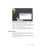


Table Of Contents
- GettingStarted_withCover.pdf
- Getting Started Inventor Fusion TP2
- Contents
- Autodesk Inventor Fusion TP2
- What is new in TP2?
- Working with Inventor Fusion User Interface
- The Ribbon
- Glyphs and Manipulators
- Marking Menu
- Selection commands
- Enhanced tooltip
- Browser and Copy/Paste
- Function Key Behavior
- Triad
- Measure
- Menu and Command Access
- Other commands in the Application Window
- Create 3D Models
- Create a Single Body
- Create Multiple Bodies
- Modify a Body
- Sketch
- Starting a Sketch
- The Sketch Plane
- The Sketch Grid
- Line/Arc Segment Creation
- Spline Creation
- Circle Creation
- Circular Arc Creation
- Rectangle Creation
- Ellipse Creation
- Polygon Creation
- Project Geometry
- Trim/Extend
- Sketch Fillet
- Sketch Inferencing
- Sketch Constraints
- Stopping a Sketch
- Sketch Profiles
- Editing a Sketch Entity
- Locking Sketch Geometry
- Features
- Find Features
- Dimensions and Body Constraints
- Error Handling
- Work Geometry
- Working with Multiple Components
- Dimensions as Annotations
- User Tags
- Import Data
- Export Data
- Materials and Model Appearance
- Modeling Paradigms
- System Requirements
- Index

The three default work planes are the YZ, ZX, and XY planes. The three default
work axes are the X, Y, and Z axes. The single default work point is the O
point which represents the value 0, 0, 0 in the model. The default work planes
and axes are based on the origin point. The following image shows the origin
geometries in the graphics window.
Note: The origin geometries are not visible by default. When a new sketch on
page 135 is started, the geometries are displayed automatically. Use the light
bulb icon to manually control the visibility of planes, axes, and point.
190 | Chapter 1 Autodesk Inventor Fusion TP2