
Quick Start


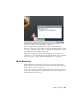


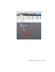
Table Of Contents
- GettingStarted_withCover.pdf
- Getting Started Inventor Fusion TP2
- Contents
- Autodesk Inventor Fusion TP2
- What is new in TP2?
- Working with Inventor Fusion User Interface
- The Ribbon
- Glyphs and Manipulators
- Marking Menu
- Selection commands
- Enhanced tooltip
- Browser and Copy/Paste
- Function Key Behavior
- Triad
- Measure
- Menu and Command Access
- Other commands in the Application Window
- Create 3D Models
- Create a Single Body
- Create Multiple Bodies
- Modify a Body
- Sketch
- Starting a Sketch
- The Sketch Plane
- The Sketch Grid
- Line/Arc Segment Creation
- Spline Creation
- Circle Creation
- Circular Arc Creation
- Rectangle Creation
- Ellipse Creation
- Polygon Creation
- Project Geometry
- Trim/Extend
- Sketch Fillet
- Sketch Inferencing
- Sketch Constraints
- Stopping a Sketch
- Sketch Profiles
- Editing a Sketch Entity
- Locking Sketch Geometry
- Features
- Find Features
- Dimensions and Body Constraints
- Error Handling
- Work Geometry
- Working with Multiple Components
- Dimensions as Annotations
- User Tags
- Import Data
- Export Data
- Materials and Model Appearance
- Modeling Paradigms
- System Requirements
- Index
In addition to explicit body constraints, you can lock a dimension to force
the model to maintain that dimension at the current value regardless of other
changes. The following video shows the basic operation:
Locked dimensions are shown in bold.
You can lock a dimension in one of two ways:
■ Double-click the dimension and change its value (pressing Enter when
done, or Escape to cancel)
■ Use the context-menu Lock command (check box) to lock the dimension
at its current value
You can uncheck the Lock check box to make a dimension unlocked again.
Only certain dimensions can be locked. If double-clicking does nothing, and
the Lock check box is not available on the context menu, then the dimension
cannot be locked.
Dimensions and explicit body constraints are solved together. No precedence
is given to one or the other.
Locked dimensions constrain edges. The adjacent faces are moved to make
the edges be the correct size and in the correct position.
When editing the value of a dimension:
■ Inventor Fusion shows you a preview of the new value. There is a built-in
delay to minimize unnecessary previews of intermediate values as you are
typing.
■ Most dimensions show an anchor glyph. This indicates which side is
grounded, and the other side will move in response to the new value of
the dimension. Move the mouse to the other side to swap the anchor.
Details
Inventor Fusion sometimes includes invisible provisional constraints to
maintain obvious perpendicularity and parallelism. If this is not appropriate,
you can move the faces slightly, before applying the constraint or locking the
dimension.
If a Move or Press/Pull operation causes an edge or face to be split, and the
edge/face has a dimension or constraint attached to it, then Inventor Fusion
will automatically apply the dimension/constraint to one of the resulting
entities. The other edge/face will not inherit any constraining behavior from
186 | Chapter 1 Autodesk Inventor Fusion TP2