
Quick Start


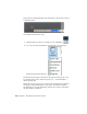


Table Of Contents
- GettingStarted_withCover.pdf
- Getting Started Inventor Fusion TP2
- Contents
- Autodesk Inventor Fusion TP2
- What is new in TP2?
- Working with Inventor Fusion User Interface
- The Ribbon
- Glyphs and Manipulators
- Marking Menu
- Selection commands
- Enhanced tooltip
- Browser and Copy/Paste
- Function Key Behavior
- Triad
- Measure
- Menu and Command Access
- Other commands in the Application Window
- Create 3D Models
- Create a Single Body
- Create Multiple Bodies
- Modify a Body
- Sketch
- Starting a Sketch
- The Sketch Plane
- The Sketch Grid
- Line/Arc Segment Creation
- Spline Creation
- Circle Creation
- Circular Arc Creation
- Rectangle Creation
- Ellipse Creation
- Polygon Creation
- Project Geometry
- Trim/Extend
- Sketch Fillet
- Sketch Inferencing
- Sketch Constraints
- Stopping a Sketch
- Sketch Profiles
- Editing a Sketch Entity
- Locking Sketch Geometry
- Features
- Find Features
- Dimensions and Body Constraints
- Error Handling
- Work Geometry
- Working with Multiple Components
- Dimensions as Annotations
- User Tags
- Import Data
- Export Data
- Materials and Model Appearance
- Modeling Paradigms
- System Requirements
- Index

The Sketch Grid has two icons associated with it. The first is a Look-At icon
that you can use to change the camera to look at the Sketch Plane if you
perform any camera operations that would change the planes orientation.
The second icon is a Stop Sketch icon that deactivates the Sketch and returns
you to the select mode.
The Grid aids in creating accurate Sketches by precisely snapping to points
defined by its spacing. A snap point is indicated by a red rectangle.
Sketch | 139