
Quick Start

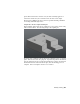


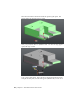


Table Of Contents
- GettingStarted_withCover.pdf
- Getting Started Inventor Fusion TP2
- Contents
- Autodesk Inventor Fusion TP2
- What is new in TP2?
- Working with Inventor Fusion User Interface
- The Ribbon
- Glyphs and Manipulators
- Marking Menu
- Selection commands
- Enhanced tooltip
- Browser and Copy/Paste
- Function Key Behavior
- Triad
- Measure
- Menu and Command Access
- Other commands in the Application Window
- Create 3D Models
- Create a Single Body
- Create Multiple Bodies
- Modify a Body
- Sketch
- Starting a Sketch
- The Sketch Plane
- The Sketch Grid
- Line/Arc Segment Creation
- Spline Creation
- Circle Creation
- Circular Arc Creation
- Rectangle Creation
- Ellipse Creation
- Polygon Creation
- Project Geometry
- Trim/Extend
- Sketch Fillet
- Sketch Inferencing
- Sketch Constraints
- Stopping a Sketch
- Sketch Profiles
- Editing a Sketch Entity
- Locking Sketch Geometry
- Features
- Find Features
- Dimensions and Body Constraints
- Error Handling
- Work Geometry
- Working with Multiple Components
- Dimensions as Annotations
- User Tags
- Import Data
- Export Data
- Materials and Model Appearance
- Modeling Paradigms
- System Requirements
- Index

Finally, you OK the command to apply the draft to the model:
Using Draft to model a part that is to be manufactured with a split mold
Sometimes, mold designers use a two-piece mold, which splits in the middle,
to remove the part after cooling. Using the same example as previously, this
time the user picks the plane shown in the following image as the neutral
plane:
Modify a Body | 129