
Quick Start

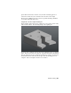


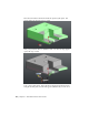


Table Of Contents
- GettingStarted_withCover.pdf
- Getting Started Inventor Fusion TP2
- Contents
- Autodesk Inventor Fusion TP2
- What is new in TP2?
- Working with Inventor Fusion User Interface
- The Ribbon
- Glyphs and Manipulators
- Marking Menu
- Selection commands
- Enhanced tooltip
- Browser and Copy/Paste
- Function Key Behavior
- Triad
- Measure
- Menu and Command Access
- Other commands in the Application Window
- Create 3D Models
- Create a Single Body
- Create Multiple Bodies
- Modify a Body
- Sketch
- Starting a Sketch
- The Sketch Plane
- The Sketch Grid
- Line/Arc Segment Creation
- Spline Creation
- Circle Creation
- Circular Arc Creation
- Rectangle Creation
- Ellipse Creation
- Polygon Creation
- Project Geometry
- Trim/Extend
- Sketch Fillet
- Sketch Inferencing
- Sketch Constraints
- Stopping a Sketch
- Sketch Profiles
- Editing a Sketch Entity
- Locking Sketch Geometry
- Features
- Find Features
- Dimensions and Body Constraints
- Error Handling
- Work Geometry
- Working with Multiple Components
- Dimensions as Annotations
- User Tags
- Import Data
- Export Data
- Materials and Model Appearance
- Modeling Paradigms
- System Requirements
- Index

If the top face of the design is selected in the Move command, the dimension
is honored, and so the bottom face moves along with the top face:
See Dimensions and Body Constraints on page 184 for more details.
Draft Command
The Draft command in Inventor Fusion can be used to modify one or more
component bodies by creating angled faces, with respect to a neutral plane.
A primary goal of this command is to be used for creating molded parts - parts
that are manufactured using an injection molding or metal casting process.
Such parts usually have faces that are slightly angled, to make removal of the
126 | Chapter 1 Autodesk Inventor Fusion TP2