
Technical data
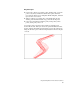

Drawing and Defining Pipe Runs
93
To draw and define a pipe run (continued)
Steps
Use
to look up
4 From the Pipes menu, choose Define Pipe
Runs ➤ Draw Pipe Run, and then type a new pipe
run name.
Select a terrain model (if a surface is defined in your
project).
You can use this surface to extract rim elevations for
the manhole structures located at each pipe run
node.
You are prompted to turn on or off the current
surface. If you want to enter elevations manually,
click Off to turn off the surface. If you want to
extract elevations from the surface, click On.
Draw and Define Pipe
Runs
5 If you are basing the run on an existing roadway
horizontal alignment, then select an alignment and
place the first point of the pipe run by specifying
the station and offset from the alignment.
If you are drawing the run manually, then specify
the first point by picking a point in the drawing or
by entering its northing/easting coordinates.
6 After you specify each point, press ENTER to Add
the point to the pipe run.
7 Type the first point’s rim elevation (if it is not being
extracted from the current terrain model).
8 Add the next point by station and offset or by
manually picking the point.
9 Continue adding points in the pipe run.
10 Type S to save your changes to the database.
The Run Alignment Association dialog box is
displayed.