
Technical data

Chapter 5 Viewing and Editing Roads in Profile View
66
To create a finished ground profile centerline
Steps
Use
to look up
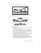
1 Draft the existing ground profile.
Overview of
Creating Profiles
2 From the Profiles menu, choose FG Centerline
Tangents ➤ Set Current Layer to set the current
layer.
Set the Current Layer for
the Finished Ground Profile
Centerline
3 From the Profiles menu, choose FG Centerline
Tangents ➤ Create Tangents to draw proposed
tangents based on stations, elevations, lengths,
and grades.
You can adjust the AutoCAD crosshairs to a
selected grade if needed. To adjust the crosshairs,
from the Profiles menu, choose FG Centerline
Tangents ➤ Crosshairs @ Grade. This command
affects the AutoCAD snap angle variable and
turns ortho mode on.
Remember, the vertical scale is exaggerated.
Autodesk Civil Design automatically factors in this
scale exaggeration.
Draw the Vertical
Alignment Tangents for
the Finished Ground
Centerline
4 From the Profiles menu, choose FG Vertical
Alignments ➤ Define FG Centerline to define the
finished ground centerline.
When you select this command, all of the layers
other than the FG Centerline layer will be turned
off so you can quickly select only the FG
Centerline objects.
Define the Finished Ground
Centerline as a Vertical
Alignment