
Technical data

Creating Finished Ground Road Profiles
65
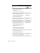
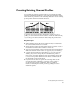
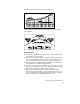
The following illustration shows a vertical tangent.
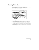
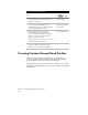
The following illustration shows a vertical curve based on passing
sight distance.
Key Concepts
■
In addition to the finished ground profile, you can design ditches
and transitions in profile view.
■
You can use the Create Tangents commands on the Profile menu,
or the AutoCAD LINE command to draw vertical tangents, but you
must use the Vertical Curves commands to draw vertical curves.
■
Other useful tools for drafting vertical tangents are available from
the Profiles
➤
FG Centerline Tangents menu.
■
In order to properly define the finished ground profiles, you must
draw them on the correct layer. Before drawing any entities, set the
current layer with the Set Current Layer command.
■
After you design finished ground elements in profile view for
transition control and ditches, you can “attach” them to the cross
sections, automatically updating the templates with the ditch and
transition elevations you established in profile view.