
Technical data

Chapter 3 Performing Hydrologic Studies
38
Using the Culvert Calculator
Autodesk Civil Design has several features that you can use to design
storm water conveyance facilities for controlling the runoff on a site.
For example, you can design outlet and inlet structures including
channels, culverts, weirs, risers, gravity pipes, orifices, and so on. This
section describes how to use the Culvert Calculator to design a culvert.
A culvert can be used to channel peak flow amounts under roadways
and other structures. You can use slope arrows and water drop trails to
determine where the runoff is most likely to cross an alignment. Then
you can place culverts at these critical locations.
Key Concepts
■
Determine the peak discharge inflow amount that the culvert has
to channel using the Rational Method, the Graphical Peak
Discharge Method, the Tabular Hydrograph Method, or an inflow
hydrograph
■
Consider outlet and tailwater control conditions
■
Consider entrance and exit loss conditions
■
Consider over-topping conditions
■
Consider minimum and maximum design flow velocities to
prevent the effects of scouring or related erosion problems
To design a culvert
Steps
Use
to look up
1 Determine the specific watershed characteristics
and design criteria, including the peak flow rate
amounts at the discharge point.
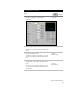
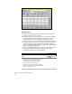
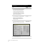
2 From the Hydrology menu, choose Settings to
display the Hydrology Tools Settings dialog box.
Change the Hydrology
Unit Settings
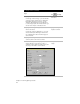
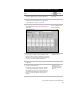
3 Click Units to specify the culvert measurement
units or click Precision to specify the required
precision settings for your units.