
Technical data

Chapter 2 Getting Started with AutoCAD Land Development Desktop
90
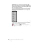
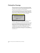
The following illustration shows the marker that is displayed over the
endpoint, and the ToolTip that explains which snap point the cursor
is snapped to.
AutoSnap works even when you set multiple object snaps. Press TAB
to cycle through the snap points on an object.
For more information, see “Changing Object Snap Settings” in the
online Help.
AutoTrack
AutoTrack is another way to specify a point in relation to existing
points by using the pointing device. AutoTrack helps you draw objects
at specific angles or with specific relationships to other objects in the
drawing.
When you turn on AutoTrack, temporary alignment paths help you
create objects at precise positions and angles. AutoTrack includes two
tracking options: polar tracking and object snap tracking. You can
turn AutoTrack on and off with the Polar and Otrack buttons on the
status bar.
Use polar tracking to track the cursor along temporary alignment
paths defined by polar angles relative to a command's From or To
points. Polar tracking is used only when ORTHO mode is turned off.
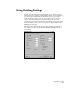
For an illustration of polar tracking, see “Using Drafting Settings” in
this chapter.
Object snap tracking works in conjunction with object snaps. You
must set an object snap before you can track from an object's snap
point. The AutoSnap aperture settings control how close you must be
to the alignment path before the path is displayed.