
Technical data

Working with Drawings
67
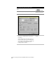
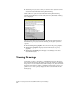
Drawing Setup Example: Setting a Base Point
and North Rotation
Before you bring points into your drawing, you may want to set the
drawing orientation. The drawing orientation settings include a base
point and north rotation. These two settings control the drawing’s
coordinate system. You can adjust both the base point so that it ties
into a known coordinate system (that you can specify on the Zone tab
of the Drawing Setup dialog box), and the north rotation so that all
your project points fit within the boundaries of your plot sheet.
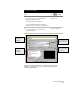
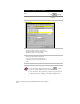
AutoCAD Land Development Desktop uses two coordinate systems for
locating points: X,Y and northing/easting. When you start a new
project, these values all default to 0 so that the Y coordinate is the
same as the northing, and the X coordinate is the same as the easting.
You can set up a base point to assign a specific northing and easting
value to a fixed X,Y location. For example, if your drawing points
begin at northing and easting coordinates of 5000,5000, then you can
set a new base point to translate these coordinates so they will fit onto
your drawing screen.
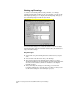
By default, North is always represented in a drawing as the top of the
screen. But you can define a different orientation of North if the
drawing layout requires it. You should typically set the north rotation
when you create a new drawing, but you can change it at any time.
You can give different drawings attached to the same project different
north rotations. This provides different views of the project point data
relative to the X,Y coordinates.