
Technical data
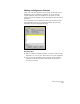

Working with Surface Output and Visualization Tools
205
Key Concepts
■
You can draw the range view as 2D solids or 3D faces, and you can
view the faces in plan or 3D perspective.
■
When using the banding methods, the program automatically
splits surface triangles to properly match the range that you define.
In other words, if you created the triangle between points that
range from 90' - 120', then the program would break this into
individual faces at 90', 100', 110', and 120'. This ensures that the
elevational banding is properly presented. This does not modify the
surface, but it only breaks the plotted faces to match the elevational
criteria.
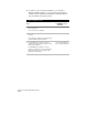
To create an elevational range view
Steps
Use
to look up
1
Select the current surface.
Make a Surface Current
2
From the Terrain menu, choose Surface
Display
➤
Elevation Settings to define the
elevational ranges, layers, and layer colors.
Where there is minimal elevational exaggeration,
you can also define vertical scaling to help see site
features.
Change the Surface
Elevation Shading Settings
3
Generate the range view by selecting an
elevational range view command. From the
Terrain menu, choose Surface Display
➤
Average -
3D Faces or Banding - 3D Faces.
Create 2D Solids Using the
Banding Method that
Shows the Elevations of
a Surface
Create 3D Faces Using the
Banding Method that
Shows the Elevations of a
Surface
4
To manage the layers on which you created
the range views, select Terrain
➤
Terrain
Layers
➤
Range Layers.
Manage the Range Layers