
Technical data

Chapter 3 Working with COGO Points
104
Changing the Point Marker Settings
When you create, insert, or import points into a drawing, the
appearance of the points varies depending on the Point Marker
settings.
The point marker settings control how your points appear in the
drawing. When you are ready to plot, you can create point labels that
can label data from external databases and that can perform
description key substitution.
Key Concepts
■
If you set the point marker size to a percentage of the screen, then
the points are always the same size on screen regardless of the
zoom level.
■
To change the AutoCAD POINT node style, use the DDPTYPE
command.
■
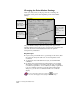
By default, AutoCAD Land Development Desktop uses northing
and easting coordinates to represent points in space. A northing
coordinate is equivalent to a Y coordinate; an easting is equivalent
to an X coordinate. From the Coords tab in the Point Settings
dialog box, you can choose a different method of coordinate
display.
For more information about point settings use to look up
“Overview of Changing the Point Settings” in the online Help.
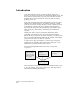
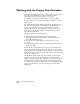
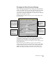
You can use a
custom marker or
the AutoCAD
POINT node style
for the marker.
You can choose a
custom marker
style for the point
node.
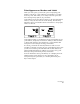
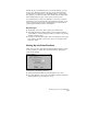
You can set the
size of the marker
in absolute units
or to a
percentage of the
screen.
You can align the
marker with the
point text
rotation.