
Technical data

Using Standard Parts
56
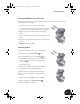
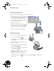
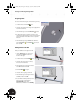
To fully constrain the quick-action lever:
1. On the Panel bar, click the Place Constraint tool.
2. In the Place Constraint dialog box, click the Angle
option.
3. In the graphics window, select the planar face of the
plate on the quick-action lever, and then select the
bottom edge of the sheet metal part as shown in the
image to the right.
4. In the Place Constraint dialog box, click OK.
Using Standard Parts
Autodesk Inventor software includes a library of standard parts that comply with ISO, ANSI, and DIN standards,
and many others. This library of standard parts includes a variety of fasteners, shaft parts, and steel shapes.
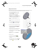
Next, you will insert two socket head bolts that are used to fasten the upper clamp to the lower clamp
weldment.
1. At the top of the Browser, double-click Clamp_complete.iam to make
the main assembly active.
2. Restore your display to an Isometric View.
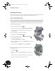
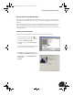
3. On the Browser title, click Model and then select Library.
This switches the Browser to display all active standard part catalogs.
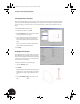
4. In the Browser, double-click Standard Parts, then Fasteners, then
Screws and Threaded Bolts, and finally Socket Head Types.
The Browser now displays all available socket head-type fasteners.
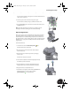
The bolt you need to insert is an ISO 4762 (Regular Thread) bolt. To find
this bolt in the list:
5. Select one of the items in the list and then type the letter I (the first letter
in ISO).
The list automatically scrolls to the first entry beginning with the letter “I”.
6. In the list, double-click ISO 4762 (Regular Thread).
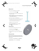
7. Select a nominal diameter of 6 mm and a nominal length of 25 mm.
INV8_TD_Book5.book Page 56 Tuesday, October 28, 2003 10:51 AM