
Technical data

Using iMate—Intelligent Mating of Components
52
Using iMate—Intelligent Mating of Components
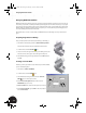
Next, you will add a hole to the sheet metal part. After you add the hole, you will add intelligence to the hole so
that other parts will constrain themselves to this hole automatically. You will also create a flat pattern that can be
used to manufacture the sheet metal part.
Adding a Hole
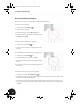
1. In the Browser, double-click Clamp_C:1 to activate the sheet
metal part.
To define the location of the hole, you must create a new sketch.
2. In the graphics window, right-click the outer face of the left
flange and choose New Sketch.
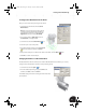
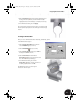
3. On the Panel bar, click Point, Hole Center and then click near
the center of the rectangular flange face.
4. Click the General Dimension tool and create one vertical and
one horizontal dimension between the hole center point and the
edges of the flange.
To ensure that the location of the hole remains centered on the
flange, you will define dimension values that use existing
dimensions and formulas.
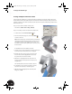
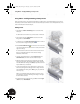
5. Select the horizontal dimension, click the right arrow, select
Show Dimensions, and then select the sheet metal part.
6. When the dimensions for the part are displayed, select the 55
dimension (the length of the flange) and then change the value
in the Edit Dimension dialog box to d4/2 (the parameter name d2
may be different in your situation).
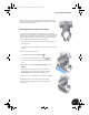
7. For the vertical dimension, select the dimension, select the 10
dimension (the height of the flange) and then change the value
in the Edit Dimension dialog box to d2/2 (again, your parameter
name may vary).
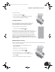
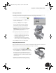
When you are finished editing the dimensions, the hole center
point should be centered on the flange. The image on the right
shows the finished sketch.
8. To finish dimensioning and sketching, press Esc and then right-
click and choose Finish Sketch.
INV8_TD_Book5.book Page 52 Tuesday, October 28, 2003 10:51 AM