
Technical data

Designing Welded Assemblies
50
Designing Welded Assemblies
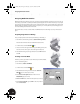
With Autodesk Inventor software, the process of creating a welded assembly is similar to the process in the real
world. First, you start with an assembly of individual parts designed to their nominal size. Next, you can prepare
those parts by removing material at the locations of the weld seams. Finally, you then weld parts together using
different weld types. After the welded assembly is complete, you can even perform post machining processes
and create drawings that include the weld seams.
Autodesk Inventor can create cosmetic welds and 3D fillet welds. In the following sections you will use both
types.
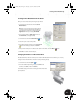
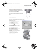
Preparing Single Parts for Welding
First, you will prepare the seam between parts Clamp_A and Clamp_B.
1. In the Browser, under Clamp_welded:1, double-click Preparations.
Notice that the Panel bar switches to Weldment Features Panel.
2. On the Panel bar, click the Chamfer tool.
3. Select once where the edges of the Clamp_A and Clamp_B meet, and
select the same location again to select the edges of both parts.
4. In the Chamfer dialog box, change the distance to 0.5 mm and then
click OK.
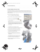
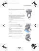
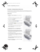
Creating a Cosmetic Weld
Now that you have prepared the location where the parts will be welded,
you can weld them together.
1. In the Browser, double-click Welds.
2. On the Panel bar, click the Weld tool.
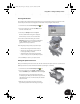
3. In the Weld Feature dialog box, ensure that the Cosmetic
Weld option is selected (see arrow 1)
4. Click the Arrow Side Symbol button and then select a
V Butt Weld type (see arrow 2).
5. Clear the Prefix next to the Arrow Side Symbol (see arrow 3).
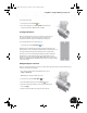
6. Click the Arrow Side tab, type 0.5 mm for the size, and then
click the General tab.
2
3
1
INV8_TD_Book5.book Page 50 Tuesday, October 28, 2003 10:51 AM