
Technical data

Creating a Sheet Metal Design
48
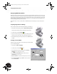
Creating an Adaptive Link Between Parts
In the transitional part (Clamp_B), you intentionally underconstrained the cutout at the bottom of the part so
that the diameter of the cutout could adapt to the outer diameter of the sheet metal part. Next, you will use an
assembly constraint to place the sheet metal part at the center of the cutout and simultaneously establish a link
between the two faces.
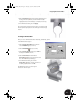
First, you need to make the welded assembly active.
•In the Browser, double-click on Clamp_welded:1.
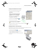
To place an assembly constraint and establish the adaptive link:
1. On the Panel bar, click the Place Constraint tool.
2. In the Place Constraint dialog box, ensure that the Mate
constraint is selected.
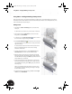
Note: In the following steps, it is important that you identify the
appropriate solution for the mate constraint. Since the face you
are selecting is cylindrical, two different solutions exist — the
face and the center axis of the cylindrical face. You want to select
the face solution.
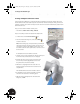
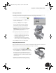
To identify the two faces for the Mate constraint:
3. Hover the cursor over the cylindrical face of the sheet metal part
for a few moments until the selection tool is displayed.
4. Click the right arrow on the selection tool until the outer
face is the only solution highlighted (the center axis of
the cylindrical face should not be visible).
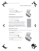
5. When the face is highlighted and the center axis is not
displayed, click the center button on the selection tool to
accept that face.
This identifies the first selection for the Mate constraint.
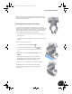
6. To identify the second selection for the Mate constraint,
select the lower cutout face on the Clamp_B part.
7. With the two faces highlighted, in the Place Constraint
dialog box, click OK.
INV8_TD_Book5.book Page 48 Tuesday, October 28, 2003 10:51 AM