
Technical data

Creating a Sheet Metal Design
44
Creating a Sheet Metal Design
Autodesk Inventor software has powerful sheet metal capabilities built right into the software. Sheet metal
designs need to take into consideration a constant thickness, bend radii, relief sizes, and so forth. Autodesk
Inventor enables you to easily manage all these sheet metal variables, and much more.
Creating a Sheet Metal Part
With Autodesk Inventor software, you can design a sheet metal part in several convenient ways. For the
purposes of this test drive, you will design a sheet metal part from a simple contour.
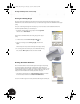
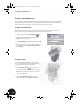
1. On the Panel bar, click the Create Component tool.
2. In the Create In-Place Component dialog box, type
Clamp_C as the new file name.
3. Select Sheet Metal.ipt as the template and then click OK.
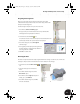
4. To define the sketch plane for the new sheet metal part,
in the Browser, under the Origin of Clamp_welded:1,
select YZ Plane.
Creating a Sketch
Once again, you start your part with a sketch. Since you
are now somewhat familiar with the following sketching
tools, we will be more brief in our descriptions.
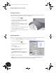
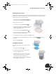
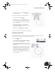
1. Use the Center Point Circle tool to sketch a circle
in the general location shown in the image to the right.
Note: The center point of the circle is not constrained
to any existing geometry.
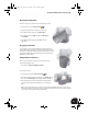
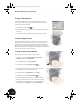
2. Use the General Dimension tool to create a
dimension on the circle with a diameter of 35 mm.
INV8_TD_Book5.book Page 44 Tuesday, October 28, 2003 10:51 AM