
Technical data

Working with Multiple Parts in an Assembly
43
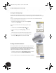
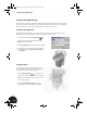
Making the Sketch Adaptive
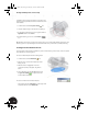
Next, you need to make this sketch adaptive.
•In the Browser, right-click Sketch3 and choose Adaptive.
The adaptivity icon is displayed next to Sketch3 in the Browser. Later in
the design process when you define a geometric relationship between
the geometry of this feature and geometry on the sheet metal part, the
size of this cutout will adapt.
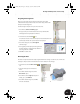
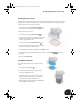
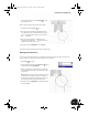
Extruding the Cutout
To finish the design of the cutout:
1. On the Panel bar, click the Extrude tool.
2. Select the circle as the profile.
3. In the Extrude dialog box, select the Cut, All, and
Centered options and then click OK.
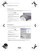
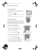
Normally, at this point you would also have to make the Clamp_B
part adaptive. However, since the ellipse from the Clamp_A part
was projected as the first sketch of Clamp_B, this part is already
adaptive. To verify that the Clamp_B part is adaptive, there should
be an adaptivity icon next to the Clamp_B part in the Browser.
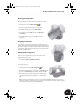
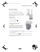
To complete the design of the thin-walled part and return to the welded assembly:
1. In the Browser, right-click Work Plane1 and then choose Visibility to clear the check mark and turn off the
visibility of the work plane.
2. On the Standard toolbar, click the Return tool to make Clamp_welded:1 the active assembly.
This completes the design of the adaptive thin-walled part. In the next section, you will create a sheet metal
part that controls the size of the lower cutout.
INV8_TD_Book5.book Page 43 Tuesday, October 28, 2003 10:51 AM