
Technical data

Working with Multiple Parts in an Assembly
42
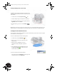
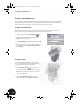
Creating a Thin-Walled Part
To reduce the weight and increase the strength of your lofted part, you
need to hollow out the part using a constant wall thickness. You also want
to keep both ends of the part open.
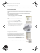
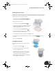
1. On the Panel bar, click the Shell tool.
2. To identify the faces to be removed, select the upper and lower planar faces
of the part.
3. In the Shell dialog box, type 1.5 for the thickness, and then click OK.
Creating an Adaptive Cutout
A circular cutout must be added at the lower portion of the part so that it can
be welded to the sheet metal part. For convenience, you can design this
circular cutout to be adaptive to the outer diameter of the sheet metal part.
Adaptive means one part automatically adapts to geometry on another part.
The first step in making this cutout adaptive is to purposely underconstrain the
size of the cutout by not providing a dimension.
Creating an Underconstrained Sketch
Again, we start creating the cutout by creating a sketch.
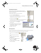
1. In the Browser, under the Origin of Clamp_B:1, right-click
YZ Plane and then choose New Sketch.
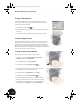
2. From the View menu, choose Slice Graphics.
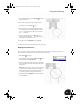
3. On the Panel bar, click the Project Geometry tool.
4. To project a reference line for the sketch, select the lower outer
circular edge (see arrow) of the Clamp_B:1 part.
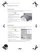
5. In the graphics window, right-click and choose Done.
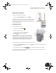
6. On the Panel bar, click the Center Point Circle tool.
7. Select the midpoint of the projected line, and then click again to
define a circle similar to the one shown in the image to the right.
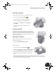
8. Press the Esc key to end the Center Point Circle tool, and then in
the graphics window, right-click and choose Finish Sketch.
INV8_TD_Book5.book Page 42 Tuesday, October 28, 2003 10:51 AM