
Technical data

Working with Multiple Parts in an Assembly
39
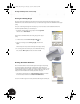
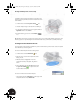
Mirroring the Tapped Hole
The lower clamp also needs two holes to match the upper clamp.
1. On the Panel bar, click the Mirror Feature tool.
2. Select the tapped hole as the feature to be mirrored.
3. In the Mirror Pattern dialog box, click Mirror Plane.
4. In the Browser, next to Origin under the part Clamp_A:1,
click YZ Plane.
5. In the Mirror Pattern dialog box, click OK to mirror the
tapped hole.
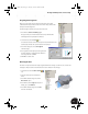
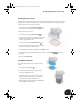
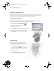
Designing a Lofted Part
You now need to create a part to handle the transition between the
lower halfshell and the sheet metal part that you will create later in this
test drive. Since both ends of this part require a different size and shape,
you will use the lofting functionality. The image to the right shows the
finished part in the assembly.
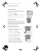
Adding Another Component
Before you create another new part, you need to make sure the
appropriate assembly is active.
•In the Browser, double-click Clamp_welded:1.
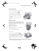
To create the new part:
1. On the Panel bar, click the Create Component tool.
2. In the Create In-Place Component dialog box, type Clamp_B for the
file name, use Standard.ipt as the template, and then click OK.
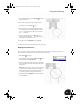
3. When prompted to select the surface for the new sketch plane,
select the bottom elliptical face of Clamp_A:1, as shown to the
right.
Tip: To rotate the part while using another tool, press and hold the F4 key and then use your mouse to
rotate the part. When you release the F4 key, you return to the previous state and can continue using the
tool. To return to your previous view, press the F5 key.
INV8_TD_Book5.book Page 39 Tuesday, October 28, 2003 10:51 AM