
Technical data

Working with Multiple Parts in an Assembly
38
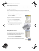
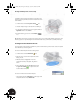
Filleting the Transition
Next, you will fillet the transition between the halfshell and the elliptical body. Although this part requires only a
simple constant fillet, Autodesk Inventor can create very complex fillets.
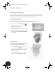
1. On the Panel bar, click the Fillet tool.
2. In the graphics window, select the two edges where
the outer face of the halfshell intersects the vertical
face of the elliptical body.
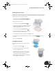
Note: You can select the opposite edge by selecting
through the model, or use the Rotate tool to change
your viewing orientation.
3. In the Fillet dialog box, select the existing radius value,
change it to 0.5 mm, and then click OK.
A constant fillet with a radius of 0.5 mm is created on both
sides of the part.
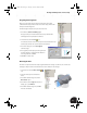
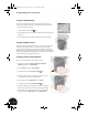
Adding Tapped Holes
Now that you have added through holes to the upper clamp, you need to add tapped holes to the lower clamp.
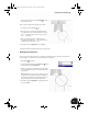
1. In the Browser, double-click Clamp_A:1 to make the lower clamp the active part.
2. On the Panel bar, click the Hole tool.
3. In the Holes dialog box, select Through All as the
termination type.
4. Select the Tapped check box.
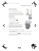
5. When the Holes dialog box expands, ensure the
Full Depth check box is checked.
6. Select ISO Metric profile for the thread type, select
6 for the nominal size, and then select M6x1 for the
pitch.
7. Click OK to create the threaded hole.
Note: The appearance of threads will not appear on the hole if you cleared the Show Reflections and
Textures check box in the Options dialog box at the beginning of this test drive.
INV8_TD_Book5.book Page 38 Tuesday, October 28, 2003 10:51 AM