
Technical data

Working with Multiple Parts in an Assembly
35
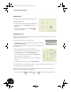
To create a new welded assembly component:
1. On the Panel bar, click the Create Component tool.
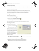
2. Important: In the Create In-Place Component dialog box, click
the arrow next to Template and select Weldment.iam.
3. Type Clamp_welded.iam as the new file name and then click
OK to close the dialog box.
The cursor changes appearance to signify that you need
to identify a reference plane for placement in the assembly.
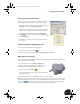
4. In the Browser, click the plus (+) sign next to Origin directly
under Clamp_complete.iam, and then click the XY Plane.
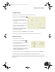
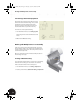
In the graphics window, the display of the clamp_top part dims, signifying that it is no longer active and
appears to be in the background. This dimming effect enables you to focus on the new part your are about to
design rather than on other parts in the assembly.
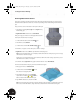
Creating the First Component in the Welded Assembly
As in real life, a welded assembly in Autodesk Inventor software is put together from several individual parts.
The first part you will design in this welded assembly is the lower shell bearing.
1. On the Panel bar, click the Create Component tool.
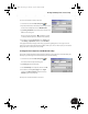
In the Create In-Place Component dialog box:
2. Type Clamp_A as the New File Name.
3. Select Standard.ipt as the template, and then click OK.
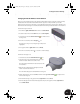
4. In the Browser, click the plus (+) sign next to Origin
directly below Clamp_welded:1, and then select the
XY Plane to place the component.
The new part is created and Sketch1 is now active.
INV8_TD_Book5.book Page 35 Tuesday, October 28, 2003 10:51 AM