
Technical data

Creating a Production Drawing
28
Creating a Production Drawing
Thus far we have created a 3D model, but what about creating technical drawings? With Autodesk Inventor
software, you can derive drawings directly from your 3D models and your drawings are fully associative to those
3D models. This means that your drawings automatically update when your 3D designs change. This also means
that you can change model dimensions in your drawings, and your 3D models automatically update.
Starting a New Drawing
To create a new drawing of your 3D part:
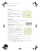
1. On the Standard toolbar, click the New tool.
2. In the Open dialog box, double-click the Standard.idw icon.
A new A3 size drawing sheet with a frame and title block is created.
Notice that the Panel bar has automatically changed to offer the appropriate Drawing Views Panel tools.
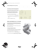
Generating the First View
To create the first view of your 3D part:
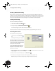
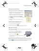
• On the Panel bar, click the Base View
tool.
The Drawing View dialog box is displayed.
By default, Autodesk Inventor suggests using
the contents of other open parts or assemblies
for the drawing view. Since the other window
contains your assembly, the default file for the
drawing view is the assembly file.
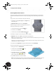
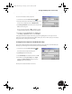
In an assembly drawing, hidden edges and
dimensions of the individual parts are not
displayed. To create a drawing of the part,
rather than the assembly:
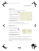
1. In the Drawing View dialog box, click the Explore Directories button next to the file selection box, select
Clamp_top.ipt from the list, and then click Open.
2. Ensure the scale is set to 1:1 and the style is set to Hidden Line .
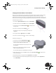
3. Move the cursor to the upper-left side of the drawing sheet, and click to place the view.
Tip: If the dialog box is in the way, simply drag it by clicking the blue title bar at the top.
INV8_TD_Book5.book Page 28 Tuesday, October 28, 2003 10:51 AM