
Technical data

Adding Design Details
26
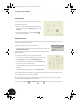
5. In the Extrude dialog box, click the Cut option, click
the down arrow under Extents and select All, click the
Centered option, and then click OK.
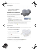
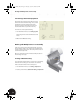
Changing the Thickness of the Bearing Shell
If you look closely at the model, you see that the bearing shell
seems to be too thick. An ideal thickness would be 2 mm. The
formula we used previously was d1-1. Since you want to
reference the diameter of the ellipse rather than the radius,
you can simply modify the equation.
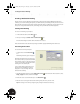
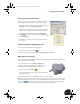
1. Since Sketch2 is still active, simply double-click the 14.5 dimension
to edit the value.
2. In the Edit Dimension dialog box, type d1*2-4 and then click the
green check mark to accept the value and close the dialog box.
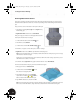
Rather than automatically updating the model after each change to the model, Autodesk Inventor enables
you to finish making your changes and then specify when the model should be updated.
3. On the Standard toolbar, click the Update tool to update the model with your changes.
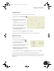
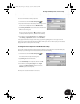
Preparing for Holes
The upper clamp requires two holes on the upper planar face so that it can be fastened to the lower clamp. The
next step is to identify the placement locations for the holes.
1. On the Standard toolbar, click the Sketch tool and
then select the upper planar elliptical face of the part.
2. On the Panel bar, click the Point, Hole Center tool
and click anywhere on the planar elliptical face.
3. Click the down arrow next to the Tangent tool and click
the Horizontal tool.
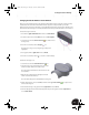
4. Select the hole center point you just created, and then
select the center point of the ellipse on the sketch plane.
5. On the Panel bar, click the General Dimension tool
and place a horizontal dimension between the two points.
6. Select the dimension, type a value of 18, and click the green check mark to accept.
7. To quit the Dimension tool, press Esc or right-click and choose Done.
INV8_TD_Book5.book Page 26 Tuesday, October 28, 2003 10:51 AM