
Technical data

Adding Design Details
21
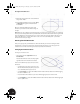
Referencing Existing Geometry
The bearing shell must maintain a geometric relationship with the elliptical solid. You can easily use existing
geometry by referencing existing dimensions or by projecting geometry onto the current sketch plane.
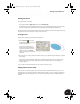
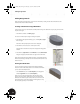
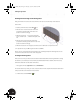
1. On the Panel bar, scroll down and click the Project
Geometry tool.
2. In the graphics window, select the upper and lower
elliptical edges of your 3D part.
Two black lines (slightly difficult to see in the image
shown on the right) are created on the sketch plane.
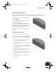
These lines are fully associative to the elliptical edges of
the part. That means these lines automatically update
when the elliptical part edges change.
Later, you will use these lines to control the size of the
bearing shell.
Sketching the Bearing Shell
To create the sketch geometry for the bearing shell:
1. On the Panel bar, click the Center Point Circle tool.
To find this tool, click the down arrow next to the Ellipse
tool.
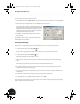
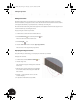
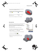
2. Move the cursor to the approximate center of the lower
projection line that you create previously.
3. When the cursor changes to a green dot, click to define
the center of the circle.
The green dot signifies that you are at the midpoint of
the line. This ensures your circle is centered on the line
you projected earlier.
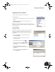
4. Move the cursor to the right and click again to create a
circle similar to the image shown on the right.
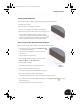
5. With the Center Point Circle tool still active, create
another slightly smaller circle using the same approach
just described.
6. To quit the Center Point Circle tool, right-click and
choose Done.
INV8_TD_Book5.book Page 21 Tuesday, October 28, 2003 10:51 AM