
Technical data

Adding Design Details
20
Adding Design Details
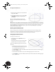
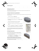
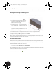
Next, you will add a bearing shell to your model. You will start by creating another sketch and then use that
sketch to make another extrusion feature.
Creating a Sketch Plane Using a Work Plane
In the previous section you activated the assembly before saving it. To add features to your part, you must make
the part active again.
• In the Browser, double-click Clamp_top:1.
To create a new sketch plane using an existing work plane:
1. In the Browser, directly below Clamp_top:1, click the plus (+) sign in
front of Origin.
The names of the principal planes and axes are displayed.
2. In the Browser, move the cursor over the plane names.
Notice that the orientation of each plane is displayed in the graphics
window.
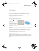
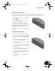
3. In the Browser, right-click the name XZ Plane and select New Sketch.
The grid is displayed, and the sketch tools appear on the Panel bar.
Notice that several elements in the Browser have a gray background. The
Browser uses shading to identify active and inactive elements. In this case,
Sketch2 is active.
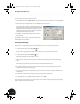
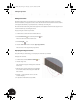
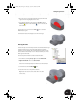
Viewing the Sketch Plane
You can see that the grid on the sketch plane interferes with the
model. To see the entire sketch plane or to work inside solid models,
you can use the Slice Graphics tool.
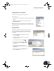
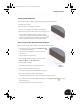
•From the View menu, choose Slice Graphics (or in the graphics
window, right-click and choose Slice Graphics).
Now you can see the entire sketch plane. The cut surface of the
model is also shown with a texture (unless you cleared the Show
Reflections and Textures option earlier). This section view slices the
model through the current sketch plane for viewing purposes only.
The actual part geometry is not modified.
INV8_TD_Book5.book Page 20 Tuesday, October 28, 2003 10:51 AM