
Technical data

Entering the Third Dimension
18
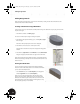
To create a parametric reference for the extrusion:
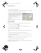
1. In the Extrude dialog box, double-click the current distance value (make sure that “mm” is also highlighted).
2. With the distance value highlighted, select the 15.5 dimension on the sketch.
The parameter d1 now appears in the Extrude dialog box as
the distance value. You have just created a link between the
height of the ellipse and the extrusion distance. If you ever
change the value of the dimension, the extrusion distance
will automatically reflect the same value.
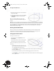
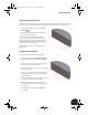
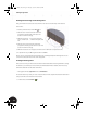
3. Click OK to close the Extrude dialog box and create the
Extrude feature.
Congratulations! You have just created your first 3D model
with Autodesk Inventor software.
Zooming and Rotating
Now it’s time to visually examine your model. In Autodesk Inventor you can easily do this at any time.
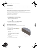
1. On the Standard toolbar, click the Zoom All tool.
The Zoom All tool adjusts the view of the model so that you can see the entire model onscreen.
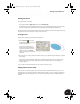
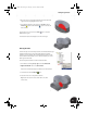
2. On the Standard toolbar, click the Rotate tool.
The Rotate tool displays an Orbit symbol as a circle.
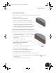
3. Move the cursor inside the Orbit circle, and then click and hold the left mouse button while moving the
cursor.
This allows you to dynamically rotate the model and view it from different directions.
4. To rotate the model about its vertical or horizontal axis, move the cursor over the quadrant lines on the
perimeter of the Orbit circle, and then drag.
5. To spin the model about an axis perpendicular to your screen, move the cursor just outside the Orbit circle,
and then drag.
6. To redefine the center of rotation, simply click at the point you want to rotate about.
7. To quit the Rotate tool, press Esc or right-click and then choose Done.
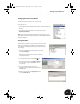
If you don’t get the view you want, you can always return to the isometric view by right-clicking in the graphics
window and then choosing Isometric View.
INV8_TD_Book5.book Page 18 Tuesday, October 28, 2003 10:51 AM