
Technical data

Entering the Third Dimension
17
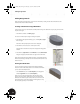
Finishing the Sketch
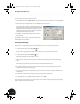
To leave the sketch environment:
• In the graphics window, right-click and then choose Finish Sketch.
Notice that the grid is no longer displayed because it is only needed during sketching. Also notice on the
Panel bar that the sketch commands have been replaced by the 3D modeling part feature tools.
By now, you will have noticed that the intuitive user interface in Autodesk Inventor makes design tasks as easy
as possible. In most cases, the next tool is only a mouse-click away.
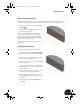
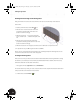
Creating a Solid
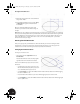
For this portion of the design, you will use the Extrude tool.
1. Click the Extrude tool to open
the Extrude dialog box. A preview of
the 3D model is shown.
Since there is currently only one
sketch, the profile is automatically
selected. If your sketch has several
profiles, you can use the Profile
option to select the profile you want
to extrude.
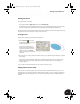
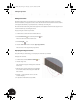
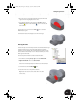
2. Move the cursor to an edge of the preview until it changes color, and then drag the extrusion to a slightly
larger height.
Notice that the value in the Extrude dialog box is automatically updated. You can also specify an exact
distance in this dialog box. In the next few steps, you will see another approach to automating the
extrusion distance.
3. Do not click OK in the Extrude dialog box, and continue to the next section.
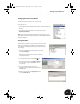
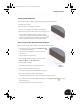
Adding a Dimension Constraint
Next, you will see an interesting way to enter the extrusion distance. With Autodesk Inventor, you can use
existing dimensions as parametric references. With parametric references, you can change the original value
and all references automatically update. You can even combine parametric references with mathematical
formulas.
INV8_TD_Book5.book Page 17 Tuesday, October 28, 2003 10:51 AM