
2011


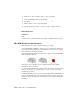


Table Of Contents
- Contents
- Get Information
- The User Interface
- Tools in the Application Window
- Other Tool Locations
- Customize the Drawing Environment
- Start and Save Drawings
- Control the Drawing Views
- Change Views
- Use Viewing Tools
- Display Multiple Views in Model Space
- Organize Drawings and Layouts
- Create Single-View Drawings (Model Space)
- Create Multiple-View Drawing Layouts (Paper Space)
- Work with Sheets in a Sheet Set
- Create and Modify Objects
- Control the Properties of Objects
- Work with Object Properties
- Work with Layers
- Work with Colors
- Work with Linetypes
- Control Lineweights
- Control the Display Properties of Certain Objects
- Use Precision Tools
- Use Coordinates and Coordinate Systems (UCS)
- Use Dynamic Input
- Snap to Locations on Objects (Object Snaps)
- Restrict Cursor Movement
- Combine or Offset Points and Coordinates
- Specify Distances
- Extract Geometric Information from Objects
- Use a Calculator
- Draw Geometric Objects
- Change Existing Objects
- Add Constraints to Geometry
- Control the Properties of Objects
- Define and Reference Blocks
- Work with Blocks
- Create and Modify Blocks
- Add Behaviors to Blocks (Dynamic Blocks)
- Overview of Dynamic Blocks
- Quick Start to Creating Dynamic Blocks
- Create and Edit Dynamic Blocks
- Add Constraints to Dynamic Blocks
- Add Action Parameters to Dynamic Blocks
- Work with 3D Models
- Create 3D Models
- Overview of 3D Modeling
- Create Solids and Surfaces from Lines and Curves
- Create Solids
- Create Surfaces
- Create Meshes
- Create Wireframe Models
- Add 3D Thickness to Objects
- Modify 3D Models
- Create Sections and 2D Drawings from 3D Models
- Create 3D Models
- Annotate Drawings
- Work with Annotations
- Hatches, Fills, and Wipeouts
- Notes and Labels
- Tables
- Dimensions and Tolerances
- Understand Basic Concepts of Dimensioning
- Use Dimension Styles
- Set the Scale for Dimensions
- Create Dimensions
- Modify Existing Dimensions
- Add Geometric Tolerances
- Plot and Publish Drawings
- Prepare Drawings for Plotting and Publishing
- Quick Start to Saving Settings for Plotting and Publishing
- Specify Page Setup Settings
- Overview of Page Setup Settings
- Select a Printer or Plotter for a Layout
- Select a Paper Size for a Layout
- Set the Plot Area of a Layout
- Adjust the Plot Offset of a Layout
- Set the Plot Scale for a Layout
- Set the Lineweight Scale for a Layout
- Select a Plot Style Table for a Layout
- Set Shaded Viewport and Plot Options for a Layout
- Determine the Drawing Orientation of a Layout
- Use the Layout Wizard to Specify Layout Settings
- Import PCP or PC2 Settings into a Layout
- Create and Use Named Page Setups
- Use Named Page Setups with Sheet Sets
- Plot Drawings
- Quick Start to Plotting
- Overview of Plotting
- Use a Page Setup to Specify Plot Settings
- Select a Printer or Plotter
- Specify the Area to Plot
- Set Paper Size
- Position the Drawing on the Paper
- Control How Objects Are Plotted
- Preview a Plot
- Plot Files to Other Formats
- Publish Drawings
- Prepare Drawings for Plotting and Publishing
- Share Data Between Files
- Reference Other Drawing Files
- Link and Embed Data (OLE)
- Work with Data in Other Formats
- Import Other File Formats
- Attach Files as Underlays
- Attach Raster Image Files
- Export Drawings to Other File Formats
- Use Drawings from Different Versions and Applications
- Extract Data from Drawings and Spreadsheets
- Access External Databases
- Overview of Using External Databases
- Access a Database from Within AutoCAD
- Link Database Records to Graphical Objects
- Use Labels to Display Database Information in the Drawing
- Use Queries to Filter Database Information
- Share Link and Label Templates and Queries with Other Users
- Work with Links in Files from Earlier Releases
- Manage Files with Autodesk Vault
- Collaborate with Others
- Protect and Sign Drawings
- Use the Internet for Collaboration
- Use Markups for Design Review
- Render Drawings
- Draw 2D Isometric Views
- Add Lighting to Your Model
- Materials and Textures
- Render 3D Objects for Realism
- Glossary
- Index

Create Composite Objects
Create composite 3D objects by combining, subtracting, or finding the
intersecting mass of two or more 3D solids, surfaces, or regions.
Composite solids are created from two or more solids, surfaces, or regions
through any of the following commands: UNION, SUBTRACT, and INTERSECT.
3D solids record a history of how they were created. This history allows you to
see the original forms that make up composite solids. For more information,
see
Display Original Forms of Composite Solids on page 1134.
Methods for Creating Composite Objects
Three methods are available for creating composite solids, surfaces, or regions:
■ Combine two or more objects.
With UNION, you can combine the total volume of two or more objects.
■ Subtract one set of solids from another.
With SUBTRACT, you can remove the common area of one set of solids
from another. For example, you can use SUBTRACT to add holes to a
mechanical part by subtracting cylinders from the object.
■ Find the common volume.
With INTERSECT, you can create a composite solid from the common
volume of two or more overlapping solids. INTERSECT removes the portions
1008 | Chapter 24 Create 3D Models