
2008


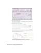


Table Of Contents
- Contents
- Part I Overview
- 01 About AutoCAD Mechanical
- AutoCAD Mechanical Software Package
- Leveraging Legacy Data
- Starting AutoCAD Mechanical
- Accessing AutoCAD Mechanical Commands
- AutoCAD Mechanical Help
- Product Support and Training Resources
- Design Features in AutoCAD Mechanical
- Mechanical Structure
- Associative Design and Detailing
- External References for Mechanical Structure
- Associative 2D Hide
- Autodesk Inventor Companion Support
- 2D Design Productivity
- Engineering Calculations
- Machinery Systems Generators
- Intelligent Production Drawing and Detailing
- Detailing Productivity
- Annotations
- Standard Mechanical Content
- Standard Parts Tools
- Collaboration
- 02 Commands in AutoCAD Mechanical
- 03 New and Revised Commands
- 01 About AutoCAD Mechanical
- Part II Design and Annotation Tools
- 04 Working with Templates
- 05 Using Mechanical Structure
- 06 Working with Layers and Layer Groups
- 07 Designing Levers
- 08 Working with Model Space and Layouts
- 09 Dimensioning
- 10 Working with 2D Hide and 2D Steel Shapes
- 11 Working with Standard Parts
- Key Terms
- Working with Standard Parts
- Inserting Screw Connections
- Copying Screw Connections with Power Copy
- Creating Screw Templates
- Editing Screw Connections with Power Edit
- Working with Power View
- Deleting with Power Erase
- Inserting Holes
- Inserting Pins
- Turning Off Centerlines in Configurations
- Hiding Construction Lines
- Simplifying Representations of Standard Parts
- 12 Working with BOMs and Parts Lists
- 13 Creating Shafts with Standard Parts
- Key Terms
- Creating Shafts
- Configuring Snap Options
- Configuring Shaft Generators
- Creating Cylindrical Shaft Sections and Gears
- Inserting Spline Profiles
- Inserting Chamfers and Fillets
- Inserting Shaft Breaks
- Creating Side Views of Shafts
- Inserting Threads on Shafts
- Editing Shafts and Inserting Sections
- Replacing Shaft Sections
- Inserting Bearings
- 14 Calculating Shafts
- Part III Engineering Calculations
- Part IV Autodesk Inventor Link
- Appendix A Layer Specifications
- Appendix B Title Block Attributes
- Appendix C Accelerator and Shortcut Keys
- Index

7 Choose the Location button.
The dialog box is hidden so you can specify a location for the cam and
the follower in the drawing.
8 Respond to the prompts as follows:
Specify center of cam: 100,100, press ENTER
Specify center of follower swing [Undo]: @100,0, press ENTER
Specify start of movement [Undo]: @90<157.36, press ENTER
Specify origin of movement diagram [Undo/Window] <Window>:
Specify a point next to the cam
Specify length of movement diagram [Undo]: @360,0, press ENTER
The cam and the follower are inserted into the drawing with the motion
diagram. Your drawing looks like this:
The Cam Design and Calculation dialog box is opened again.
392 | Chapter 20 Designing and Calculating Cams