
2008


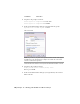
Table Of Contents
- Contents
- Part I Overview
- 01 About AutoCAD Mechanical
- AutoCAD Mechanical Software Package
- Leveraging Legacy Data
- Starting AutoCAD Mechanical
- Accessing AutoCAD Mechanical Commands
- AutoCAD Mechanical Help
- Product Support and Training Resources
- Design Features in AutoCAD Mechanical
- Mechanical Structure
- Associative Design and Detailing
- External References for Mechanical Structure
- Associative 2D Hide
- Autodesk Inventor Companion Support
- 2D Design Productivity
- Engineering Calculations
- Machinery Systems Generators
- Intelligent Production Drawing and Detailing
- Detailing Productivity
- Annotations
- Standard Mechanical Content
- Standard Parts Tools
- Collaboration
- 02 Commands in AutoCAD Mechanical
- 03 New and Revised Commands
- 01 About AutoCAD Mechanical
- Part II Design and Annotation Tools
- 04 Working with Templates
- 05 Using Mechanical Structure
- 06 Working with Layers and Layer Groups
- 07 Designing Levers
- 08 Working with Model Space and Layouts
- 09 Dimensioning
- 10 Working with 2D Hide and 2D Steel Shapes
- 11 Working with Standard Parts
- Key Terms
- Working with Standard Parts
- Inserting Screw Connections
- Copying Screw Connections with Power Copy
- Creating Screw Templates
- Editing Screw Connections with Power Edit
- Working with Power View
- Deleting with Power Erase
- Inserting Holes
- Inserting Pins
- Turning Off Centerlines in Configurations
- Hiding Construction Lines
- Simplifying Representations of Standard Parts
- 12 Working with BOMs and Parts Lists
- 13 Creating Shafts with Standard Parts
- Key Terms
- Creating Shafts
- Configuring Snap Options
- Configuring Shaft Generators
- Creating Cylindrical Shaft Sections and Gears
- Inserting Spline Profiles
- Inserting Chamfers and Fillets
- Inserting Shaft Breaks
- Creating Side Views of Shafts
- Inserting Threads on Shafts
- Editing Shafts and Inserting Sections
- Replacing Shaft Sections
- Inserting Bearings
- 14 Calculating Shafts
- Part III Engineering Calculations
- Part IV Autodesk Inventor Link
- Appendix A Layer Specifications
- Appendix B Title Block Attributes
- Appendix C Accelerator and Shortcut Keys
- Index

Key Terms
DefinitionTerm
A contour that is covered by another contour or by objects that are lying behind
another contour, in the 3D sense. A background may be a foreground for an
additional contour.
background
Objects which are lying in front of another contour, in the 3D sense. A fore-
ground may also be a background for an additional contour.
foreground
Line that is not visible in a specified view. For example, in a front view, lines
behind the front plane are not visible.
hidden line
Steel shapes are standardized steel geometries and profiles that are used for
steel and plant construction.
steel shapes
Working with 2D Hide and 2D Steel Shapes
Use the AM2DHIDE command when mechanical structure is not enabled. Use
AMSHIDE when mechanical structure is enabled. For this exercise you work
with AM2DHIDE.
Before you begin this tutorial...
This tutorial requires the mechanical browser. If the mechanical browser is
not visible:
1 Enter AMBROWSER in the command prompt and press ENTER.
2 When prompted, enter ON and press ENTER.
Opening the initial drawing
To open a drawing
1 Open the file tut_steelshape.dwg in the acadm\tutorial folder.
186 | Chapter 10 Working with 2D Hide and 2D Steel Shapes