
6.0


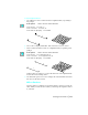


Table Of Contents
- Getting Started with Autodesk® Mechanical Desktop®
- Autodesk® Mechanical Desktop® Tutorials
- Using the Tutorials
- Creating Parametric Sketches
- Constraining Sketches
- Creating Sketched Features
- Key Terms
- Basic Concepts of Sketched Features
- Creating Extruded Features
- Editing Extruded Features
- Creating Loft Features
- Editing Loft Features
- Creating Revolved Features
- Editing Revolved Features
- Creating Face Splits
- Editing Face Splits
- Creating Sweep Features
- Editing Sweep Features
- Creating Bend Features
- Editing Bend Features
- Creating Work Features
- Creating Placed Features
- Key Terms
- Basic Concepts of Placed Features
- Creating Hole Features
- Creating Thread Features
- Editing Hole Features
- Editing Thread Features
- Creating Face Drafts
- Editing Face Drafts
- Creating Fillet Features
- Editing Fillet Features
- Creating Chamfer Features
- Editing Chamfer Features
- Creating Shell Features
- Editing Shell Features
- Creating Surface Cut Features
- Editing Surface Cut Features
- Creating Pattern Features
- Editing Pattern Features
- Editing Array Features
- Creating Copied Features
- Editing Copied Features
- Creating Combined Features
- Editing Combined Features
- Creating Part Splits
- Editing Part Splits
- Using Design Variables
- Creating Parts
- Creating Drawing Views
- Creating Shells
- Creating Table Driven Parts
- Assembling Parts
- Combining Parts
- Assembling Complex Models
- Key Terms
- Basic Concepts of Complex Assemblies
- Starting the Assembly Process
- Creating Local and External Parts
- Applying Assembly Constraints
- Creating New Parts
- Creating Subassemblies
- Completing Assemblies
- Editing Mechanical Desktop Parts
- Reloading External References
- Reviewing Assembly Models
- Creating Bills of Material
- Finishing Drawings for Plotting
- Creating and Editing Surfaces
- Combining Parts and Surfaces
- Surfacing Wireframe Models
- Key Terms
- Basic Concepts of Surfacing Wireframe Models
- Surfacing Wireframe Models
- Creating Trimmed Planar Surfaces
- Joining Surfaces on Complex Shapes
- Creating Swept and Projected Surfaces
- Creating Complex Swept Surfaces
- Using Projection to Create Surfaces
- Using Advanced Surfacing Techniques
- Viewing Completed Surfaced Models
- Working with Standard Parts
- Creating Shafts
- Calculating Stress on 3D Parts
- Toolbar Icons
- Desktop Tools
- Part Modeling
- Part Modeling ‰ New Part
- Part Modeling ‰ New Sketch Plane
- Part Modeling ‰ 2D Sketching
- Part Modeling ‰ 2D Constraints
- Part Modeling ‰ Profile a Sketch
- Part Modeling ‰ Sketched Features
- Part Modeling ‰ Placed Features
- Part Modeling ‰ Work Features
- Part Modeling ‰ Power Dimensioning
- Part Modeling ‰ Edit Feature
- Part Modeling ‰ Update Part
- Part Modeling ‰ Part Visibility
- Part Modeling ‰ Options
- Toolbody Modeling
- Assembly Modeling
- Surface Modeling
- Surface Modeling ‰ AutoSurf Options
- Surface Modeling ‰ Swept Surface
- Surface Modeling ‰ Loft U Surface
- Surface Modeling ‰ Blended Surface
- Surface Modeling ‰ Flow Wires
- Surface Modeling ‰ Object Visibility
- Surface Modeling ‰ Surface Display
- Surface Modeling ‰ Stitches Surfaces
- Surface Modeling ‰ Grip Point Placement
- Surface Modeling ‰ Lengthen Surface
- Surface Modeling ‰ Extract Surface Loop
- Surface Modeling ‰ Edit Augmented Line
- Surface Modeling ‰ Wire Direction
- Scene
- Drawing Layout
- Mechanical View
- Index

562 | Chapter 19 Creating and Editing Surfaces
Use the Extents option of ZOOM to redisplay all of the wireframes and select
the object for the next exercise.
Next, you create a blended surface from two surfaces and lines. To create a
blended surface from four objects, make the selections in the order shown;
the objects cannot be selected in consecutive order.
To blend surfaces and lines
1 Use
AMBLEND to create a surface from two surfaces and two lines, responding
to the prompts.
Desktop Menu Surface ➤ Create Surface ➤ Blend
Select first wire: Select surface (1)
Select second wire: Select surface (2)
Enter an option [Next/Accept] <Accept>: Press
ENTER
Select third wire [Weights]: Select wire (3)
Select fourth wire: Select wire (4)
The new surface is created between the original surfaces and lines.
2 Use the Extents option of
ZOOM to redisplay all of the wireframes and select
the object for the next exercise.
Next, you create two surfaces, each blended from two augmented lines.
1
4
3
2