
6.0


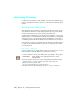


Table Of Contents
- Getting Started with Autodesk® Mechanical Desktop®
- Autodesk® Mechanical Desktop® Tutorials
- Using the Tutorials
- Creating Parametric Sketches
- Constraining Sketches
- Creating Sketched Features
- Key Terms
- Basic Concepts of Sketched Features
- Creating Extruded Features
- Editing Extruded Features
- Creating Loft Features
- Editing Loft Features
- Creating Revolved Features
- Editing Revolved Features
- Creating Face Splits
- Editing Face Splits
- Creating Sweep Features
- Editing Sweep Features
- Creating Bend Features
- Editing Bend Features
- Creating Work Features
- Creating Placed Features
- Key Terms
- Basic Concepts of Placed Features
- Creating Hole Features
- Creating Thread Features
- Editing Hole Features
- Editing Thread Features
- Creating Face Drafts
- Editing Face Drafts
- Creating Fillet Features
- Editing Fillet Features
- Creating Chamfer Features
- Editing Chamfer Features
- Creating Shell Features
- Editing Shell Features
- Creating Surface Cut Features
- Editing Surface Cut Features
- Creating Pattern Features
- Editing Pattern Features
- Editing Array Features
- Creating Copied Features
- Editing Copied Features
- Creating Combined Features
- Editing Combined Features
- Creating Part Splits
- Editing Part Splits
- Using Design Variables
- Creating Parts
- Creating Drawing Views
- Creating Shells
- Creating Table Driven Parts
- Assembling Parts
- Combining Parts
- Assembling Complex Models
- Key Terms
- Basic Concepts of Complex Assemblies
- Starting the Assembly Process
- Creating Local and External Parts
- Applying Assembly Constraints
- Creating New Parts
- Creating Subassemblies
- Completing Assemblies
- Editing Mechanical Desktop Parts
- Reloading External References
- Reviewing Assembly Models
- Creating Bills of Material
- Finishing Drawings for Plotting
- Creating and Editing Surfaces
- Combining Parts and Surfaces
- Surfacing Wireframe Models
- Key Terms
- Basic Concepts of Surfacing Wireframe Models
- Surfacing Wireframe Models
- Creating Trimmed Planar Surfaces
- Joining Surfaces on Complex Shapes
- Creating Swept and Projected Surfaces
- Creating Complex Swept Surfaces
- Using Projection to Create Surfaces
- Using Advanced Surfacing Techniques
- Viewing Completed Surfaced Models
- Working with Standard Parts
- Creating Shafts
- Calculating Stress on 3D Parts
- Toolbar Icons
- Desktop Tools
- Part Modeling
- Part Modeling ‰ New Part
- Part Modeling ‰ New Sketch Plane
- Part Modeling ‰ 2D Sketching
- Part Modeling ‰ 2D Constraints
- Part Modeling ‰ Profile a Sketch
- Part Modeling ‰ Sketched Features
- Part Modeling ‰ Placed Features
- Part Modeling ‰ Work Features
- Part Modeling ‰ Power Dimensioning
- Part Modeling ‰ Edit Feature
- Part Modeling ‰ Update Part
- Part Modeling ‰ Part Visibility
- Part Modeling ‰ Options
- Toolbody Modeling
- Assembly Modeling
- Surface Modeling
- Surface Modeling ‰ AutoSurf Options
- Surface Modeling ‰ Swept Surface
- Surface Modeling ‰ Loft U Surface
- Surface Modeling ‰ Blended Surface
- Surface Modeling ‰ Flow Wires
- Surface Modeling ‰ Object Visibility
- Surface Modeling ‰ Surface Display
- Surface Modeling ‰ Stitches Surfaces
- Surface Modeling ‰ Grip Point Placement
- Surface Modeling ‰ Lengthen Surface
- Surface Modeling ‰ Extract Surface Loop
- Surface Modeling ‰ Edit Augmented Line
- Surface Modeling ‰ Wire Direction
- Scene
- Drawing Layout
- Mechanical View
- Index

392 | Chapter 15 Creating Table Driven Parts
3 Continue on the command line to add a power dimension to the fillet at the
bottom of the long leg:
(Single) Specify first extension line origin or [Angular/Options/Baseline/Chain/
Update] <Select>: Press
ENTER
Select arc, line, circle, or dimension: Specify the arc
Enter an option [Next/Accept} <Accept>: Press
ENTER
Specify dimension line location or [Linear/Diameter/Options]:
Specify a location for the dimension
(Single) Specify first extension line origin or [Angular/Options/Baseline/Chain/
Update] <Select>: Press
ENTER
Select arc, line, circle, or dimension <Exit>: Specify the dimension
4 In the Power Dimensioning dialog box, specify tb*.75 for the dimension text.
Choose OK.
5 Continue on the command line.
Select arc, line, circle, or dimension <Exit>: Press
ENTER