
6.0


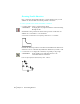
Table Of Contents
- Getting Started with Autodesk® Mechanical Desktop®
- Autodesk® Mechanical Desktop® Tutorials
- Using the Tutorials
- Creating Parametric Sketches
- Constraining Sketches
- Creating Sketched Features
- Key Terms
- Basic Concepts of Sketched Features
- Creating Extruded Features
- Editing Extruded Features
- Creating Loft Features
- Editing Loft Features
- Creating Revolved Features
- Editing Revolved Features
- Creating Face Splits
- Editing Face Splits
- Creating Sweep Features
- Editing Sweep Features
- Creating Bend Features
- Editing Bend Features
- Creating Work Features
- Creating Placed Features
- Key Terms
- Basic Concepts of Placed Features
- Creating Hole Features
- Creating Thread Features
- Editing Hole Features
- Editing Thread Features
- Creating Face Drafts
- Editing Face Drafts
- Creating Fillet Features
- Editing Fillet Features
- Creating Chamfer Features
- Editing Chamfer Features
- Creating Shell Features
- Editing Shell Features
- Creating Surface Cut Features
- Editing Surface Cut Features
- Creating Pattern Features
- Editing Pattern Features
- Editing Array Features
- Creating Copied Features
- Editing Copied Features
- Creating Combined Features
- Editing Combined Features
- Creating Part Splits
- Editing Part Splits
- Using Design Variables
- Creating Parts
- Creating Drawing Views
- Creating Shells
- Creating Table Driven Parts
- Assembling Parts
- Combining Parts
- Assembling Complex Models
- Key Terms
- Basic Concepts of Complex Assemblies
- Starting the Assembly Process
- Creating Local and External Parts
- Applying Assembly Constraints
- Creating New Parts
- Creating Subassemblies
- Completing Assemblies
- Editing Mechanical Desktop Parts
- Reloading External References
- Reviewing Assembly Models
- Creating Bills of Material
- Finishing Drawings for Plotting
- Creating and Editing Surfaces
- Combining Parts and Surfaces
- Surfacing Wireframe Models
- Key Terms
- Basic Concepts of Surfacing Wireframe Models
- Surfacing Wireframe Models
- Creating Trimmed Planar Surfaces
- Joining Surfaces on Complex Shapes
- Creating Swept and Projected Surfaces
- Creating Complex Swept Surfaces
- Using Projection to Create Surfaces
- Using Advanced Surfacing Techniques
- Viewing Completed Surfaced Models
- Working with Standard Parts
- Creating Shafts
- Calculating Stress on 3D Parts
- Toolbar Icons
- Desktop Tools
- Part Modeling
- Part Modeling ‰ New Part
- Part Modeling ‰ New Sketch Plane
- Part Modeling ‰ 2D Sketching
- Part Modeling ‰ 2D Constraints
- Part Modeling ‰ Profile a Sketch
- Part Modeling ‰ Sketched Features
- Part Modeling ‰ Placed Features
- Part Modeling ‰ Work Features
- Part Modeling ‰ Power Dimensioning
- Part Modeling ‰ Edit Feature
- Part Modeling ‰ Update Part
- Part Modeling ‰ Part Visibility
- Part Modeling ‰ Options
- Toolbody Modeling
- Assembly Modeling
- Surface Modeling
- Surface Modeling ‰ AutoSurf Options
- Surface Modeling ‰ Swept Surface
- Surface Modeling ‰ Loft U Surface
- Surface Modeling ‰ Blended Surface
- Surface Modeling ‰ Flow Wires
- Surface Modeling ‰ Object Visibility
- Surface Modeling ‰ Surface Display
- Surface Modeling ‰ Stitches Surfaces
- Surface Modeling ‰ Grip Point Placement
- Surface Modeling ‰ Lengthen Surface
- Surface Modeling ‰ Extract Surface Loop
- Surface Modeling ‰ Edit Augmented Line
- Surface Modeling ‰ Wire Direction
- Scene
- Drawing Layout
- Mechanical View
- Index

90 | Chapter 7 Constraining Sketches
Showing Constraint Symbols
You can change the parametric relationships of the lines by modifying
geometric or dimensional constraints. Because geometric constraints control
the overall shape of the sketch, you cannot safely make any changes until
you know the current geometric constraints. Therefore, the next step is to
show the symbols.
To show constraint symbols
1 Use
AMSHOWCON to display constraint symbols, responding to the prompt.
Context Menu In the graphics area, right-click and choose 2D
Constraints ➤ Show Constraints.
Enter an option [All/Select/Next/eXit] <eXit>: Enter a
Parallel constraints exist between lines 0, 2, 4 and 6. Lines 1, 3, 5, and 7 have
horizontal constraints. Lines 3 and 7 are also collinear and equal in length.
You begin reshaping your sketch by removing the parallel constraints.
To understand the constraints, look at symbol P0 (on line 2). This symbol
indicates that line 2 is parallel to line 0.