
6.0


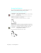
Table Of Contents
- Getting Started with Autodesk® Mechanical Desktop®
- Autodesk® Mechanical Desktop® Tutorials
- Using the Tutorials
- Creating Parametric Sketches
- Constraining Sketches
- Creating Sketched Features
- Key Terms
- Basic Concepts of Sketched Features
- Creating Extruded Features
- Editing Extruded Features
- Creating Loft Features
- Editing Loft Features
- Creating Revolved Features
- Editing Revolved Features
- Creating Face Splits
- Editing Face Splits
- Creating Sweep Features
- Editing Sweep Features
- Creating Bend Features
- Editing Bend Features
- Creating Work Features
- Creating Placed Features
- Key Terms
- Basic Concepts of Placed Features
- Creating Hole Features
- Creating Thread Features
- Editing Hole Features
- Editing Thread Features
- Creating Face Drafts
- Editing Face Drafts
- Creating Fillet Features
- Editing Fillet Features
- Creating Chamfer Features
- Editing Chamfer Features
- Creating Shell Features
- Editing Shell Features
- Creating Surface Cut Features
- Editing Surface Cut Features
- Creating Pattern Features
- Editing Pattern Features
- Editing Array Features
- Creating Copied Features
- Editing Copied Features
- Creating Combined Features
- Editing Combined Features
- Creating Part Splits
- Editing Part Splits
- Using Design Variables
- Creating Parts
- Creating Drawing Views
- Creating Shells
- Creating Table Driven Parts
- Assembling Parts
- Combining Parts
- Assembling Complex Models
- Key Terms
- Basic Concepts of Complex Assemblies
- Starting the Assembly Process
- Creating Local and External Parts
- Applying Assembly Constraints
- Creating New Parts
- Creating Subassemblies
- Completing Assemblies
- Editing Mechanical Desktop Parts
- Reloading External References
- Reviewing Assembly Models
- Creating Bills of Material
- Finishing Drawings for Plotting
- Creating and Editing Surfaces
- Combining Parts and Surfaces
- Surfacing Wireframe Models
- Key Terms
- Basic Concepts of Surfacing Wireframe Models
- Surfacing Wireframe Models
- Creating Trimmed Planar Surfaces
- Joining Surfaces on Complex Shapes
- Creating Swept and Projected Surfaces
- Creating Complex Swept Surfaces
- Using Projection to Create Surfaces
- Using Advanced Surfacing Techniques
- Viewing Completed Surfaced Models
- Working with Standard Parts
- Creating Shafts
- Calculating Stress on 3D Parts
- Toolbar Icons
- Desktop Tools
- Part Modeling
- Part Modeling ‰ New Part
- Part Modeling ‰ New Sketch Plane
- Part Modeling ‰ 2D Sketching
- Part Modeling ‰ 2D Constraints
- Part Modeling ‰ Profile a Sketch
- Part Modeling ‰ Sketched Features
- Part Modeling ‰ Placed Features
- Part Modeling ‰ Work Features
- Part Modeling ‰ Power Dimensioning
- Part Modeling ‰ Edit Feature
- Part Modeling ‰ Update Part
- Part Modeling ‰ Part Visibility
- Part Modeling ‰ Options
- Toolbody Modeling
- Assembly Modeling
- Surface Modeling
- Surface Modeling ‰ AutoSurf Options
- Surface Modeling ‰ Swept Surface
- Surface Modeling ‰ Loft U Surface
- Surface Modeling ‰ Blended Surface
- Surface Modeling ‰ Flow Wires
- Surface Modeling ‰ Object Visibility
- Surface Modeling ‰ Surface Display
- Surface Modeling ‰ Stitches Surfaces
- Surface Modeling ‰ Grip Point Placement
- Surface Modeling ‰ Lengthen Surface
- Surface Modeling ‰ Extract Surface Loop
- Surface Modeling ‰ Edit Augmented Line
- Surface Modeling ‰ Wire Direction
- Scene
- Drawing Layout
- Mechanical View
- Index

88 | Chapter 7 Constraining Sketches
Applying Geometric Constraints
When constraining a sketch, begin by defining its overall shape before defining
its size. Geometric constraints specify the orientation and relationship of the
geometric elements. For example
■ Constraints that specify orientation indicate whether an element is hori-
zontal or vertical.
■ Constraints that determine relationships specify whether two elements
are perpendicular, parallel, tangent, collinear, concentric, projected,
joined, have the same X or Y coordinate location, or have the same radius.
Mechanical Desktop displays geometric constraints as letter symbols. If the
constraint specifies a relationship between two elements, the letter symbol is
followed by the number of the sketch element to which the constraint is
related. In the example below,
■ The start point of the arc (0) has a fix constraint. This point is anchored
and will not move when changes are made to the sketch constraints.
■ The lines (2, 3, 4, and 6) have constraint symbols of either H (horizontal)
or V (vertical).
■ All lines except one are tangent to at least one of the arcs (0 and 1). Each
symbol T (tangent) is followed by the number of the arc to which it is
tangent.
■ Each arc is tangent to its connecting lines, as shown by T constraint
symbols, and the arcs have the same radius, as indicated by the R
constraint symbols.