AutoCAD LT 2011 Preview Guide AutoCAD LT® software is a leader in 2D drafting productivity and data reliability. Now, new features in AutoCAD LT 2011 bring you more options for precise control of your 2D drawings. Improve the appearance of your drawings with transparent objects and layers, and manage object visibility by hiding or isolating objects, independent of layer. Create and edit hatches faster with easier access to hatch tools.
Table of Contents User Interface ............................................................................................................................................... 3 Drawing Window .................................................................................................................................... 3 The Ribbon.............................................................................................................................................. 4 Quick Access Toolbar .......
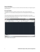
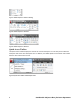
User Interface AutoCAD LT 2011 offers a variety of user interface enhancements that enable you to design with greater ease and efficiency. Drawing Window The drawing window has been updated in AutoCAD LT 2011 to display a dark gray background in modelspace. You can easily modify the drawing window color from the Display tab of the Options dialog box. The traditional dot grid has been replaced with horizontal and vertical gridlines to more closely represent engineering graph paper.
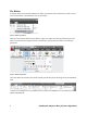
The Ribbon A new pull-down menu has been added to the ribbon cycle button at the end of the list of tabs. You can minimize the ribbon to panel buttons, tabs, or panel titles. Figure 2. Ribbon cycle options When you minimize the ribbon to panel buttons, large icons appear for each panel. Hovering over the button causes the panel to expand, similar to the behavior you see when the ribbon is minimized to panel titles. Figure 3.
On the View ribbon tab, the Windows panel includes new User Interface and Toolbar controls that enable you to easily toggle the display of the Navigation Bar, the Text Window, and toolbars. The status bar controls, although no longer on the Windows panel, are still easily accessible from the status bar. Figure 5. View ribbon tab Customizable ribbon functionality in the Customize User Interface dialog box is enhanced to include new Fold panels.
Figure 7. Ribbon Fold panel -- Default or Floating Figure 8. Ribbon Fold panel -- Maximum Figure 9. Ribbon Fold panel -- Minimum Quick Access Toolbar The Quick Access toolbar displays the name of the current workspace. You can easily select a different workspace and access other workspace tools. In addition, the default Quick Access toolbar now includes both the Save and the Save As tools. Figure 10.
Navigation AutoCAD LT 2011 includes a new Navigation Bar with the frequently used navigation tools Autodesk® SteeringWheels®, Pan, and Zoom. It replaces the navigation tools that were previously accessible on the status bar. You can control the display of the Navigation Bar for individual workspaces via a property in the CUI dialog box. Figure 11. Navigation bar and CUI Editor UCS Icon The UCS icon has been updated.
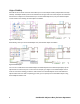
Object Visibility AutoCAD LT 2011 includes new tools that enable you to control object visibility independent from layer visibility. The Object Visibility tools are accessible from the right-click menu when objects are selected as well as when no objects are selected. When you use the Isolate Objects tool, only the selected objects remain visible in the drawing. All other objects are hidden. Figure 13. Isolated objects Alternatively, when you use the Hide Objects tool, the selected objects are hidden.
Figure 15. End object isolation The OBJECTISOLATIONMODE system variable controls whether isolated/hidden objects persist between drawing sessions. A light-bulb icon on the status bar indicates whether object isolation is active in the drawing. Figure 16. Object Isolation Status Icon Object Selection The new Select Similar tool enables you to select an object and automatically include all other objects of the same type and with the same properties, in a new selection set.
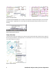
A Settings option (accessible when you enter SELECTSIMILAR at the command line) enables you to specify which properties to filter. If only the Layer property is enabled when you select a circle, for example, AutoCAD LT automatically selects all circles on the same layer as the one you selected. If both the Layer and Linetype properties are enabled, however, AutoCAD LT selects only the circles on the same layer and with the same linetype as the selected one. Figure 18.
Easily select overlapping objects using the new selection cycling functionality. You can enable selection cycling from a control on the status bar. When you try to select an object that overlaps other objects, AutoCAD LT displays a list of all the overlapping objects. As you pass the cursor over an object in the list, the relevant object in the drawing highlights. Figure 19.
Document Transparency AutoCAD LT 2011 includes a new transparency property that enables you to apply transparency to objects and layers in the same way you apply colors, linetypes, and lineweights. Figure 21. Transparent Objects You can set transparency by layer, by block, or individually for an object. The default transparency value for layers and objects is 0, and you can set it as high as 90.
You can set transparency for individual objects just like color and linetype. Setting a transparency value for an individual object overrides the layer transparency setting for that object. You can access object transparency from a number of places: the Properties palette, Quick Properties, or the ribbon. The new CETRANSPARENCY system variable sets the transparency property for new objects. Figure 23.
Prior to AutoCAD LT 2011, images had a setting, also called “transparency,” that controlled whether the background of a bitonal image was clear or opaque. This property has been renamed to “background transparency” to distinguish it from the new “transparency” property. You can apply both background and object transparencies to images in AutoCAD LT 2011. Hatches and Gradients The Hatch command received several enhancements in AutoCAD LT 2011 for faster creation and editing of hatch objects.
You can also see the result of each click as you pick points or objects in the drawing. Keep in mind that even though it looks as though a hatch was created as you clicked, it will not actually be a separate object unless you have the “Create Separate Hatches” option on. Figure 28. Hatch preview after clicking AutoCAD LT 2011 continues to expand object grip functionality with a new center grip for direct manipulation of hatch objects.
Other hatch grip behavior has not changed, except that “stretch” is now the default action for the secondary or middle grips on a non-associative hatch. Figure 30. Stretch hatch boundary Hatches now support a background color in addition to line color. This enables you to have the effect of layering hatches in one object. Figure 31. Hatch with background color You now also have the option to set a hatch’s layer before you create it.
The command HATCHTOBACK has been introduced in response to an item on the AUGI wishlist. Similar to TEXTTOFRONT, HATCHTOBACK sends hatches underneath all other objects in the drawing. “Send Hatches to Back” is available on the Modify panel of the Home tab under the Draw Order flyout, along with “Bring Text to Front” and “Bring Dimensions to Front.” Figure 32. Send Hatches to Back tool The new system variable MIRRHATCH enables you to mirror hatches while retaining their orientation.
Polylines Polyline objects in AutoCAD LT 2011 now have extra grips to make editing them easier than ever. In addition to the familiar primary grips located at the end of each polyline segment, there are now secondary grips located at the midpoint of each segment. These grips, like the new hatch grips, are multifunctional. The available functions can be seen by hovering over a grip, and you can choose an option directly from the menu that appears. Figure 34.
Splines Splines have been updated in AutoCAD LT 2011 to provide more flexibility and control. You can define a spline using fit points or control vertices (CV). CV splines are more appropriate if you will be using them with 3D NURBS (non-uniform rational b-spline) surfaces. Figure 36.
Easily switch methods, add and remove points, or edit endpoint tangencies using intuitive grip menus. Figure 38. Spline grip menus The SPLINEDIT command also has several new options, including improved Edit Vertex options. You can now easily add “kinks” or sharp corners to a spline. Figure 39. Spline with kink You can now use the JOIN command to connect lines, arcs, polylines, 3D polylines, and helixes to splines, as long as they are all contiguous (in other words, they share a common endpoint).
External References The selection of externally referenced files has been enhanced in AutoCAD LT 2011. When you select a reference object in the drawing (xrefs, images, DWFTM, DGN, PDF, data extraction tables), the corresponding reference is selected in the External References palette. Similarly, if you select file references from the External References palette, the references are highlighted (but not selected) in the drawing, assuming they are visible in the current view.
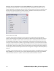
Figure 41. User Preference tab of the Options dialog The Default Scale List dialog box is similar to the existing Edit Scale List dialog, which edits the scales in the drawing. However, the Default Scale List dialog box includes additional controls for you to specify if the default scales are metric or imperial. Figure 42.
When you reset the scales list in a drawing, you are prompted to select Metric scales, Imperial scales, or both. The default choice is governed by the MEASUREMENT variable in the drawing. When you create a new drawing without specifying a template, AutoCAD LT adds metric or imperial scales based on the MEASUREMENT variable. When you create a new drawing based on a template, the scales in the template appear in the new drawing. The scales in the registry are not imported.
Text Alignment in Linetypes AutoCAD LT 2011 now makes it possible to maintain linetype readability in any orientation. Figure 45. Alignment of text in a linetype The linetypes included with AutoCAD LT 2011 behave this way by default. To update your own custom linetypes, you need to change the rotation option to U, for “upright”. (Other possible values for the rotation option are R, for “relative,” and A, for “absolute.
New to AutoCAD LT 2011 There are a few features in AutoCAD LT 2011 that will be familiar to long-time AutoCAD users, but that have been unavailable in AutoCAD LT until now. • • • • Gradient hatches are now supported, and can be found in the pattern list on the Hatch Creation and Hatch Editor contextual ribbon tabs. Quick Dimension, available on the Dimensions panel of the Annotate tab, is a useful tool for creating a series of baseline or continued dimensions for selected objects.
Online Help System AutoCAD LT 2011 includes web-based help, which you can launch from the Help icon on the InfoCenter. Figure 48. Online help system A control on the System tab of the Options dialog box allows you to disable the online help. Doing so displays a local version of the AutoCAD Help system. Autodesk, AutoCAD, AutoCAD LT, DWF, and SteeringWheels are registered trademarks or trademarks of Autodesk, Inc., and/or its subsidiaries and/or affiliates in the USA and/or other countries.