
2013

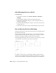


Table Of Contents
- Contents
- Get Information
- The User Interface
- Start and Save Drawings
- Control the Drawing Views
- Organize Drawings and Layouts
- Create Single-View Drawings (Model Space)
- Create Multiple-View Drawing Layouts (Paper Space)
- Work with Layouts in a Project
- Create and Modify Objects
- Control the Properties of Objects
- Use Precision Tools
- Work with the User Coordinate System (UCS)
- Enter Coordinates to Specify Points
- Use Dynamic Input
- Snap to Locations on Objects (Object Snaps)
- Restrict Cursor Movement
- Combine or Offset Points and Coordinates
- Specify Distances
- Extract Geometric Information from Objects
- Use a Calculator
- Create Objects
- Select and Modify Objects
- Select Objects
- Correct Mistakes
- Erase Objects
- Cut, Copy, and Paste with the Clipboard
- Modify Objects
- Add Constraints to Geometry
- Define and Reference Blocks
- Work with 3D Models
- Create 3D Models
- Overview of 3D Modeling
- Create Solids and Surfaces from Lines and Curves
- Create Solids
- Create Surfaces
- Create Meshes
- Create Wireframe Models
- Add 3D Thickness to Objects
- Modify 3D Models
- Create Sections and Drawings from 3D Models
- Create 3D Models
- Annotate Drawings
- Work with Annotations
- Overview of Annotations
- Scale Annotations
- Overview of Scaling Annotations
- Set Annotation Scale
- Create Annotative Objects
- Display Annotative Objects
- Add and Modify Scale Representations
- Set Orientation for Annotations
- Hatches, Fills, and Wipeouts
- Notes and Labels
- Overview of Notes and Labels
- Create Text
- Create Leaders
- Use Fields in Text
- Work with Text Styles
- Change Text
- Check Spelling
- Format Multiline Text at the Command Prompt
- Tables
- Dimensions and Tolerances
- Understand Basic Concepts of Dimensioning
- Use Dimension Styles
- Set the Scale for Dimensions
- Create Dimensions
- Modify Existing Dimensions
- Add Geometric Tolerances
- Work with Annotations
- Plot and Publish Drawings
- Specify Settings for Plotting
- Save Plot Settings as Named Page Setups
- Reuse Named Page Setups
- Specify Page Setup Settings
- Select a Printer or Plotter for a Layout
- Select a Paper Size for a Layout
- Determine the Drawing Orientation of a Layout
- Set the Plot Area of a Layout
- Adjust the Plot Offset of a Layout
- Set the Plot Scale for a Layout
- Set the Lineweight Scale for a Layout
- Select a Plot Style Table for a Layout
- Set Shaded Viewport and Plot Options for a Layout
- Named Page Setups with Projects
- Print or Plot Drawings
- Overview of Plotting
- Use a Page Setup to Specify Plot Settings
- Select a Printer or Plotter
- Specify the Area to Plot
- Set Paper Size
- Position the Drawing on the Paper
- Control How Objects Are Plotted
- Preview a Plot
- Plot Files to Other Formats
- Publish Drawings
- Specify Settings for Plotting
- Share Data Between Files
- Reference Other Drawing Files
- Work with Data in Other Formats
- Import Other File Formats
- Attach PDF Files as Underlays
- Attach Raster Image Files
- Export Drawings to Other File Formats
- Use Drawings from Different Versions and Applications
- Collaborate with Others
- Render Drawings
- Draw 2D Isometric Views
- Add Lighting to Your Model
- Materials and Textures
- Render 3D Objects for Realism
- Glossary
- Index

network environment. By overlaying an xref, you can see how your drawing
relates to the drawings of other groups without changing your drawing by
attaching an xref.
In the following illustration, several people are working on drawings referenced
by master.dwg. The person working on a.dwg needs to see the work being
completed by the person working on b.dwg, but does not want to xref b.dwg
because it would then appear twice in master.dwg. Instead, the person overlays
b.dwg, which is not included when a.dwg is referenced by master.dwg.
NOTE When using the parametric drawing feature, you can only constrain objects
in the drawing to the insertion point of an Xref, and not its nested objects.
Relative Saved Paths and Nested Xrefs
The saved path for an xref can be a full path, a relative (partially specified)
path, or no path. For a nested xref, a relative path always references the
location of its immediate host and not necessarily the currently open drawing.
See also:
Set Paths to Referenced Drawings (page 647)
Set Paths to Referenced Drawings
You can view and edit the file name and path used when locating a particular
drawing reference (xref). Use this option if the referenced file has been moved
to a different folder or renamed since it was first attached.
Reference Other Drawing Files | 647