
2013


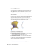


Table Of Contents
- Contents
- Get Information
- The User Interface
- Start and Save Drawings
- Control the Drawing Views
- Organize Drawings and Layouts
- Create Single-View Drawings (Model Space)
- Create Multiple-View Drawing Layouts (Paper Space)
- Work with Layouts in a Project
- Create and Modify Objects
- Control the Properties of Objects
- Use Precision Tools
- Work with the User Coordinate System (UCS)
- Enter Coordinates to Specify Points
- Use Dynamic Input
- Snap to Locations on Objects (Object Snaps)
- Restrict Cursor Movement
- Combine or Offset Points and Coordinates
- Specify Distances
- Extract Geometric Information from Objects
- Use a Calculator
- Create Objects
- Select and Modify Objects
- Select Objects
- Correct Mistakes
- Erase Objects
- Cut, Copy, and Paste with the Clipboard
- Modify Objects
- Add Constraints to Geometry
- Define and Reference Blocks
- Work with 3D Models
- Create 3D Models
- Overview of 3D Modeling
- Create Solids and Surfaces from Lines and Curves
- Create Solids
- Create Surfaces
- Create Meshes
- Create Wireframe Models
- Add 3D Thickness to Objects
- Modify 3D Models
- Create Sections and Drawings from 3D Models
- Create 3D Models
- Annotate Drawings
- Work with Annotations
- Overview of Annotations
- Scale Annotations
- Overview of Scaling Annotations
- Set Annotation Scale
- Create Annotative Objects
- Display Annotative Objects
- Add and Modify Scale Representations
- Set Orientation for Annotations
- Hatches, Fills, and Wipeouts
- Notes and Labels
- Overview of Notes and Labels
- Create Text
- Create Leaders
- Use Fields in Text
- Work with Text Styles
- Change Text
- Check Spelling
- Format Multiline Text at the Command Prompt
- Tables
- Dimensions and Tolerances
- Understand Basic Concepts of Dimensioning
- Use Dimension Styles
- Set the Scale for Dimensions
- Create Dimensions
- Modify Existing Dimensions
- Add Geometric Tolerances
- Work with Annotations
- Plot and Publish Drawings
- Specify Settings for Plotting
- Save Plot Settings as Named Page Setups
- Reuse Named Page Setups
- Specify Page Setup Settings
- Select a Printer or Plotter for a Layout
- Select a Paper Size for a Layout
- Determine the Drawing Orientation of a Layout
- Set the Plot Area of a Layout
- Adjust the Plot Offset of a Layout
- Set the Plot Scale for a Layout
- Set the Lineweight Scale for a Layout
- Select a Plot Style Table for a Layout
- Set Shaded Viewport and Plot Options for a Layout
- Named Page Setups with Projects
- Print or Plot Drawings
- Overview of Plotting
- Use a Page Setup to Specify Plot Settings
- Select a Printer or Plotter
- Specify the Area to Plot
- Set Paper Size
- Position the Drawing on the Paper
- Control How Objects Are Plotted
- Preview a Plot
- Plot Files to Other Formats
- Publish Drawings
- Specify Settings for Plotting
- Share Data Between Files
- Reference Other Drawing Files
- Work with Data in Other Formats
- Import Other File Formats
- Attach PDF Files as Underlays
- Attach Raster Image Files
- Export Drawings to Other File Formats
- Use Drawings from Different Versions and Applications
- Collaborate with Others
- Render Drawings
- Draw 2D Isometric Views
- Add Lighting to Your Model
- Materials and Textures
- Render 3D Objects for Realism
- Glossary
- Index
Create non-planar, network surfaces with the SURFNETWORK command.
Network surfaces are similar to lofted surfaces in that they are created in the
space between several curves in the U and V directions. The curves can be
surface or solid edge subobjects. When you create the surface you can specify
the tangency and bulge magnitude of the surface edges.
See also:
Overview of Creating Surfaces (page 369)
Blend a Surface
Create a transition surface between two existing surfaces.
Use SURFBLEND to create a new surface between existing surfaces and solids.
When you blend surfaces together, specify the surface continuity and bulge
magnitude for the start and end edges.
See also:
Overview of Creating Surfaces (page 369)
Patch a Surface
Create a surface by patching a closed surface or curve.
Use SURFPATCH to create a surface inside a closed curve (such as a closed
spline) that is another surface’s edge. You can also draw a guide curve to
constrain the shape of the patch surface with the constrain geometry option.
When you patch surfaces, specify the continuity and bulge magnitude.
See also:
Overview of Creating Surfaces (page 369)
Offset a Surface
Create a parallel surface a specified distance from the original surface.
With SURFOFFSET specify the offset distance and whether or not the offset
surface maintains associativity with the original surface. You can also specify
Create 3D Models | 375