
2013


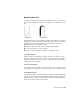


Table Of Contents
- Contents
- Get Information
- The User Interface
- Start and Save Drawings
- Control the Drawing Views
- Organize Drawings and Layouts
- Create Single-View Drawings (Model Space)
- Create Multiple-View Drawing Layouts (Paper Space)
- Work with Layouts in a Project
- Create and Modify Objects
- Control the Properties of Objects
- Use Precision Tools
- Work with the User Coordinate System (UCS)
- Enter Coordinates to Specify Points
- Use Dynamic Input
- Snap to Locations on Objects (Object Snaps)
- Restrict Cursor Movement
- Combine or Offset Points and Coordinates
- Specify Distances
- Extract Geometric Information from Objects
- Use a Calculator
- Create Objects
- Select and Modify Objects
- Select Objects
- Correct Mistakes
- Erase Objects
- Cut, Copy, and Paste with the Clipboard
- Modify Objects
- Add Constraints to Geometry
- Define and Reference Blocks
- Work with 3D Models
- Create 3D Models
- Overview of 3D Modeling
- Create Solids and Surfaces from Lines and Curves
- Create Solids
- Create Surfaces
- Create Meshes
- Create Wireframe Models
- Add 3D Thickness to Objects
- Modify 3D Models
- Create Sections and Drawings from 3D Models
- Create 3D Models
- Annotate Drawings
- Work with Annotations
- Overview of Annotations
- Scale Annotations
- Overview of Scaling Annotations
- Set Annotation Scale
- Create Annotative Objects
- Display Annotative Objects
- Add and Modify Scale Representations
- Set Orientation for Annotations
- Hatches, Fills, and Wipeouts
- Notes and Labels
- Overview of Notes and Labels
- Create Text
- Create Leaders
- Use Fields in Text
- Work with Text Styles
- Change Text
- Check Spelling
- Format Multiline Text at the Command Prompt
- Tables
- Dimensions and Tolerances
- Understand Basic Concepts of Dimensioning
- Use Dimension Styles
- Set the Scale for Dimensions
- Create Dimensions
- Modify Existing Dimensions
- Add Geometric Tolerances
- Work with Annotations
- Plot and Publish Drawings
- Specify Settings for Plotting
- Save Plot Settings as Named Page Setups
- Reuse Named Page Setups
- Specify Page Setup Settings
- Select a Printer or Plotter for a Layout
- Select a Paper Size for a Layout
- Determine the Drawing Orientation of a Layout
- Set the Plot Area of a Layout
- Adjust the Plot Offset of a Layout
- Set the Plot Scale for a Layout
- Set the Lineweight Scale for a Layout
- Select a Plot Style Table for a Layout
- Set Shaded Viewport and Plot Options for a Layout
- Named Page Setups with Projects
- Print or Plot Drawings
- Overview of Plotting
- Use a Page Setup to Specify Plot Settings
- Select a Printer or Plotter
- Specify the Area to Plot
- Set Paper Size
- Position the Drawing on the Paper
- Control How Objects Are Plotted
- Preview a Plot
- Plot Files to Other Formats
- Publish Drawings
- Specify Settings for Plotting
- Share Data Between Files
- Reference Other Drawing Files
- Work with Data in Other Formats
- Import Other File Formats
- Attach PDF Files as Underlays
- Attach Raster Image Files
- Export Drawings to Other File Formats
- Use Drawings from Different Versions and Applications
- Collaborate with Others
- Render Drawings
- Draw 2D Isometric Views
- Add Lighting to Your Model
- Materials and Textures
- Render 3D Objects for Realism
- Glossary
- Index

SPLINE and BLEND create curves called nonuniform rational B-splines (NURBS),
referred to as splines for simplicity.
By default, a spline is a series of blended curve segments of degree 3 (also
called cubic) polynomials. Cubic splines are the most common, and mimic
the splines that are created manually using flexible strips that are shaped by
weights at data points.
In the following example, SPLINE was used to create the highlighted boundary
of the concrete walkway.
BLEND was used to create splines between lines and arcs for a golf course
design. The resulting splines are tangent to the selected lines and curves
without changing the lengths of the selected objects.
Splines are also used for creating solids and surfaces for 3D modeling. For more
information, see
Create Solids and Surfaces from Lines and Curves (page 342).
Understand Control Vertices and Fit Points
You can create or edit splines using either control vertices, or fit points. The
spline on the left displays control vertices along a control polygon, and the
spline on the right displays fit points.
The options available in SPLINE depend on which method is used to create
the spline.
Create Objects | 211