
2013


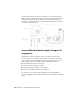
Table Of Contents
- Contents
- Get Information
- The User Interface
- Start and Save Drawings
- Control the Drawing Views
- Organize Drawings and Layouts
- Create Single-View Drawings (Model Space)
- Create Multiple-View Drawing Layouts (Paper Space)
- Work with Layouts in a Project
- Create and Modify Objects
- Control the Properties of Objects
- Use Precision Tools
- Work with the User Coordinate System (UCS)
- Enter Coordinates to Specify Points
- Use Dynamic Input
- Snap to Locations on Objects (Object Snaps)
- Restrict Cursor Movement
- Combine or Offset Points and Coordinates
- Specify Distances
- Extract Geometric Information from Objects
- Use a Calculator
- Create Objects
- Select and Modify Objects
- Select Objects
- Correct Mistakes
- Erase Objects
- Cut, Copy, and Paste with the Clipboard
- Modify Objects
- Add Constraints to Geometry
- Define and Reference Blocks
- Work with 3D Models
- Create 3D Models
- Overview of 3D Modeling
- Create Solids and Surfaces from Lines and Curves
- Create Solids
- Create Surfaces
- Create Meshes
- Create Wireframe Models
- Add 3D Thickness to Objects
- Modify 3D Models
- Create Sections and Drawings from 3D Models
- Create 3D Models
- Annotate Drawings
- Work with Annotations
- Overview of Annotations
- Scale Annotations
- Overview of Scaling Annotations
- Set Annotation Scale
- Create Annotative Objects
- Display Annotative Objects
- Add and Modify Scale Representations
- Set Orientation for Annotations
- Hatches, Fills, and Wipeouts
- Notes and Labels
- Overview of Notes and Labels
- Create Text
- Create Leaders
- Use Fields in Text
- Work with Text Styles
- Change Text
- Check Spelling
- Format Multiline Text at the Command Prompt
- Tables
- Dimensions and Tolerances
- Understand Basic Concepts of Dimensioning
- Use Dimension Styles
- Set the Scale for Dimensions
- Create Dimensions
- Modify Existing Dimensions
- Add Geometric Tolerances
- Work with Annotations
- Plot and Publish Drawings
- Specify Settings for Plotting
- Save Plot Settings as Named Page Setups
- Reuse Named Page Setups
- Specify Page Setup Settings
- Select a Printer or Plotter for a Layout
- Select a Paper Size for a Layout
- Determine the Drawing Orientation of a Layout
- Set the Plot Area of a Layout
- Adjust the Plot Offset of a Layout
- Set the Plot Scale for a Layout
- Set the Lineweight Scale for a Layout
- Select a Plot Style Table for a Layout
- Set Shaded Viewport and Plot Options for a Layout
- Named Page Setups with Projects
- Print or Plot Drawings
- Overview of Plotting
- Use a Page Setup to Specify Plot Settings
- Select a Printer or Plotter
- Specify the Area to Plot
- Set Paper Size
- Position the Drawing on the Paper
- Control How Objects Are Plotted
- Preview a Plot
- Plot Files to Other Formats
- Publish Drawings
- Specify Settings for Plotting
- Share Data Between Files
- Reference Other Drawing Files
- Work with Data in Other Formats
- Import Other File Formats
- Attach PDF Files as Underlays
- Attach Raster Image Files
- Export Drawings to Other File Formats
- Use Drawings from Different Versions and Applications
- Collaborate with Others
- Render Drawings
- Draw 2D Isometric Views
- Add Lighting to Your Model
- Materials and Textures
- Render 3D Objects for Realism
- Glossary
- Index

Reorient the View of a Model with ViewCube
The ViewCube tool offers many intuitive ways to reorient the view of a model.
Reorient the Current View
You can reorient the current view of a model by clicking predefined areas on
the ViewCube tool or dragging the ViewCube tool.
The ViewCube tool provides twenty-six defined parts to click and change the
current view of a model. The twenty-six defined parts are categorized into
three groups: corner, edge, and face. Of the twenty-six defined parts, six of
the parts represent standard orthogonal views of a model: top, bottom, front,
back, left, and right. Orthogonal views are set by clicking one of the faces on
the ViewCube tool.
You use the other twenty defined parts to access angled views of a model.
Clicking one of the corners on the ViewCube tool reorients the current view
of the model to a three-quarter view, based on a viewpoint defined by three
sides of the model. Clicking one of the edges reorients the view of the model
to a half view based on two sides of the model.
The outline of the ViewCube tool helps you identify the form of orientation
it is in: standard or fixed. When the ViewCube tool is in standard orientation,
not orientated to one of the twenty-six predefined parts, its outline is displayed
as dashed. The ViewCube tool is outlined in a solid continuous line when it
is constrained to one of the predefined views.
FaceCornerEdge
Drag or Click the ViewCube Tool
You can also click and drag the ViewCube tool to reorient the view of a model
to a custom view other than one of the twenty-six predefined parts. If you
drag the ViewCube tool close to one of the preset orientations and it is set to
snap to the closest view, the ViewCube tool rotates to the closest preset
orientation.
The ViewCube tool reorients the object’s view around a pivot point.
When the object is unselected, drag the ViewCube tool to reorient the
object’s view around the pivot point displayed at the center of the view.
Use Viewing Tools | 77