
2012

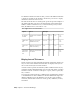


Table Of Contents
- Contents
- Get Information
- The User Interface
- Start and Save Drawings
- Control the Drawing Views
- Organize Drawings and Layouts
- Create and Modify Objects
- Control the Properties of Objects
- Use Precision Tools
- Work with the User Coordinate System (UCS)
- Enter Coordinates to Specify Points
- Use Dynamic Input
- Snap to Locations on Objects (Object Snaps)
- Restrict Cursor Movement
- Combine or Offset Points and Coordinates
- Specify Distances
- Extract Geometric Information from Objects
- Use a Calculator
- Create Objects
- Select and Modify Objects
- Select Objects
- Correct Mistakes
- Erase Objects
- Cut, Copy, and Paste with the Clipboard
- Modify Objects
- Add Constraints to Geometry
- Define and Reference Blocks
- Work with 3D Models
- Create 3D Models
- Overview of 3D Modeling
- Create Solids and Surfaces from Lines and Curves
- Create Solids
- Create Surfaces
- Create Meshes
- Create Wireframe Models
- Add 3D Thickness to Objects
- Modify 3D Models
- Create Sections and Drawings from 3D Models
- Create 3D Models
- Annotate Drawings
- Work with Annotations
- Overview of Annotations
- Scale Annotations
- Overview of Scaling Annotations
- Set Annotation Scale
- Create Annotative Objects
- Display Annotative Objects
- Add and Modify Scale Representations
- Set Orientation for Annotations
- Hatches, Fills, and Wipeouts
- Notes and Labels
- Tables
- Dimensions and Tolerances
- Understand Basic Concepts of Dimensioning
- Use Dimension Styles
- Set the Scale for Dimensions
- Create Dimensions
- Modify Existing Dimensions
- Add Geometric Tolerances
- Work with Annotations
- Plot and Publish Drawings
- Specify Settings for Plotting
- Save Plot Settings as Named Page Setups
- Reuse Named Page Setups
- Specify Page Setup Settings
- Select a Printer or Plotter for a Layout
- Select a Paper Size for a Layout
- Determine the Drawing Orientation of a Layout
- Set the Plot Area of a Layout
- Adjust the Plot Offset of a Layout
- Set the Plot Scale for a Layout
- Set the Lineweight Scale for a Layout
- Select a Plot Style Table for a Layout
- Set Shaded Viewport and Plot Options for a Layout
- Print or Plot Drawings
- Overview of Plotting
- Use a Page Setup to Specify Plot Settings
- Select a Printer or Plotter
- Specify the Area to Plot
- Set Paper Size
- Position the Drawing on the Paper
- Control How Objects Are Plotted
- Preview a Plot
- Plot Files to Other Formats
- Publish Drawings
- Specify Settings for Plotting
- Share Data Between Files
- Reference Other Drawing Files
- Work with Data in Other Formats
- Collaborate with Others
- Render Drawings
- Draw 2D Isometric Views
- Add Lighting to Your Model
- Materials and Textures
- Render 3D Objects for Realism
- Glossary
- Index

Setting dimension scale depends on how you lay out your drawing. There are
three methods used to create dimensions in a drawing layout:
Dimension in model space for printing in model space. This is
the traditional method used with single-view drawings. To create
dimensions that are scaled correctly for printing, set the DIMSCALE system
variable to the inverse of the intended print scale. For example, if the print
scale is 1/4, set DIMSCALE to 4.
. This was the preferred method for complex, multiple-view drawings prior
to AutoCAD 2002. Use this method when the dimensions in a drawing
need to be referenced by other drawings (xrefs) or when creating isometric
dimensions in 3D isometric views. To prevent the dimensions in one layout
viewport from being displayed in other layout viewports, create a
dimensioning layer for each layout viewport that is frozen in all other
layout viewports. To create dimensions that are scaled automatically for
display in a paper space layout, set the DIMSCALE system variable to 0.
Dimension in layouts. This is the simplest dimensioning method.
Dimensions are created in paper space by selecting model space objects or
by specifying object snap locations on model space objects. By default,
associativity between paper space dimensions and model space objects is
maintained. No additional scaling is required for dimensions created in a
paper space layout: DIMLFAC and DIMSCALE do not need to be changed
from their default value of 1.0000.
NOTE When you dimension model space objects in paper space using associative
dimensions, dimension values for the display scale of each viewport are
automatically adjusted. This adjustment is combined with the current setting for
DIMLFAC and is reported by the LIST command as a dimension style override. For
nonassociative dimensions, you must set DIMLFAC manually.
See also:
Draw, Scale, and Annotate in Model Space (page 96)
Scale Views in Layout Viewports (page 105)
Scale Annotations (page 548)
Create Dimensions
You can create all of the standard types of dimensions.
650 | Chapter 9 Annotate Drawings