
2012

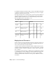


Table Of Contents
- Contents
- Get Information
- The User Interface
- Start and Save Drawings
- Control the Drawing Views
- Organize Drawings and Layouts
- Create and Modify Objects
- Control the Properties of Objects
- Use Precision Tools
- Work with the User Coordinate System (UCS)
- Enter Coordinates to Specify Points
- Use Dynamic Input
- Snap to Locations on Objects (Object Snaps)
- Restrict Cursor Movement
- Combine or Offset Points and Coordinates
- Specify Distances
- Extract Geometric Information from Objects
- Use a Calculator
- Create Objects
- Select and Modify Objects
- Select Objects
- Correct Mistakes
- Erase Objects
- Cut, Copy, and Paste with the Clipboard
- Modify Objects
- Add Constraints to Geometry
- Define and Reference Blocks
- Work with 3D Models
- Create 3D Models
- Overview of 3D Modeling
- Create Solids and Surfaces from Lines and Curves
- Create Solids
- Create Surfaces
- Create Meshes
- Create Wireframe Models
- Add 3D Thickness to Objects
- Modify 3D Models
- Create Sections and Drawings from 3D Models
- Create 3D Models
- Annotate Drawings
- Work with Annotations
- Overview of Annotations
- Scale Annotations
- Overview of Scaling Annotations
- Set Annotation Scale
- Create Annotative Objects
- Display Annotative Objects
- Add and Modify Scale Representations
- Set Orientation for Annotations
- Hatches, Fills, and Wipeouts
- Notes and Labels
- Tables
- Dimensions and Tolerances
- Understand Basic Concepts of Dimensioning
- Use Dimension Styles
- Set the Scale for Dimensions
- Create Dimensions
- Modify Existing Dimensions
- Add Geometric Tolerances
- Work with Annotations
- Plot and Publish Drawings
- Specify Settings for Plotting
- Save Plot Settings as Named Page Setups
- Reuse Named Page Setups
- Specify Page Setup Settings
- Select a Printer or Plotter for a Layout
- Select a Paper Size for a Layout
- Determine the Drawing Orientation of a Layout
- Set the Plot Area of a Layout
- Adjust the Plot Offset of a Layout
- Set the Plot Scale for a Layout
- Set the Lineweight Scale for a Layout
- Select a Plot Style Table for a Layout
- Set Shaded Viewport and Plot Options for a Layout
- Print or Plot Drawings
- Overview of Plotting
- Use a Page Setup to Specify Plot Settings
- Select a Printer or Plotter
- Specify the Area to Plot
- Set Paper Size
- Position the Drawing on the Paper
- Control How Objects Are Plotted
- Preview a Plot
- Plot Files to Other Formats
- Publish Drawings
- Specify Settings for Plotting
- Share Data Between Files
- Reference Other Drawing Files
- Work with Data in Other Formats
- Collaborate with Others
- Render Drawings
- Draw 2D Isometric Views
- Add Lighting to Your Model
- Materials and Textures
- Render 3D Objects for Realism
- Glossary
- Index

For dimension distances less than one unit, you can set the dimension distance
to display in sub units. If the distance is shown in m, you can set to display
distances less than one m in cm or mm.
The table shows the effect of selecting each option and provides examples of
the architectural units style. If feet are included with a fractional inch, the
number of inches is indicated as zero, no matter which option you select.
Thus, the dimension 4'-3/4" becomes 4'-0 3/4".
Zero suppression for feet and inches
ExamplesEffectOption
1'-0
3/4"
1'-0"0'-6"0'-0 1/2"Includes zero feet and zero
inches
No options
selected
1'-0
3/4"
1'0'-6"0'-0 1/2"Suppresses zero inches
(includes zero feet)
0 Inches selec-
ted
1'-0
3/4"
1'-0"6"1/2"Suppresses zero feet (in-
cludes zero inches)
0 Feet selec-
ted
1'-0
3/4"
1'6"1/2"Suppresses zero feet and
zero inches
0 Feet and 0
Inches selec-
ted
Display Lateral Tolerances
Lateral tolerances are values indicating the amount a measured distance can
vary. You can control whether lateral tolerances are displayed and you can
choose from several styles of lateral tolerances.
A lateral tolerance specifies the amount by which a dimension can vary. By
specifying tolerances in manufacturing, you can control the degree of accuracy
needed for a feature. A feature is some aspect of a part, such as a point, line,
axis, or surface.
You can apply tolerances directly to a dimension by appending the tolerances
to the dimension text. These dimension tolerances indicate the largest and
smallest permissible size of the dimension. You can also apply geometric
tolerances, which indicate deviations of form, profile, orientation, location,
and runout.
646 | Chapter 9 Annotate Drawings