
2012


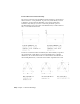


Table Of Contents
- Contents
- Get Information
- The User Interface
- Start and Save Drawings
- Control the Drawing Views
- Organize Drawings and Layouts
- Create and Modify Objects
- Control the Properties of Objects
- Use Precision Tools
- Work with the User Coordinate System (UCS)
- Enter Coordinates to Specify Points
- Use Dynamic Input
- Snap to Locations on Objects (Object Snaps)
- Restrict Cursor Movement
- Combine or Offset Points and Coordinates
- Specify Distances
- Extract Geometric Information from Objects
- Use a Calculator
- Create Objects
- Select and Modify Objects
- Select Objects
- Correct Mistakes
- Erase Objects
- Cut, Copy, and Paste with the Clipboard
- Modify Objects
- Add Constraints to Geometry
- Define and Reference Blocks
- Work with 3D Models
- Create 3D Models
- Overview of 3D Modeling
- Create Solids and Surfaces from Lines and Curves
- Create Solids
- Create Surfaces
- Create Meshes
- Create Wireframe Models
- Add 3D Thickness to Objects
- Modify 3D Models
- Create Sections and Drawings from 3D Models
- Create 3D Models
- Annotate Drawings
- Work with Annotations
- Overview of Annotations
- Scale Annotations
- Overview of Scaling Annotations
- Set Annotation Scale
- Create Annotative Objects
- Display Annotative Objects
- Add and Modify Scale Representations
- Set Orientation for Annotations
- Hatches, Fills, and Wipeouts
- Notes and Labels
- Tables
- Dimensions and Tolerances
- Understand Basic Concepts of Dimensioning
- Use Dimension Styles
- Set the Scale for Dimensions
- Create Dimensions
- Modify Existing Dimensions
- Add Geometric Tolerances
- Work with Annotations
- Plot and Publish Drawings
- Specify Settings for Plotting
- Save Plot Settings as Named Page Setups
- Reuse Named Page Setups
- Specify Page Setup Settings
- Select a Printer or Plotter for a Layout
- Select a Paper Size for a Layout
- Determine the Drawing Orientation of a Layout
- Set the Plot Area of a Layout
- Adjust the Plot Offset of a Layout
- Set the Plot Scale for a Layout
- Set the Lineweight Scale for a Layout
- Select a Plot Style Table for a Layout
- Set Shaded Viewport and Plot Options for a Layout
- Print or Plot Drawings
- Overview of Plotting
- Use a Page Setup to Specify Plot Settings
- Select a Printer or Plotter
- Specify the Area to Plot
- Set Paper Size
- Position the Drawing on the Paper
- Control How Objects Are Plotted
- Preview a Plot
- Plot Files to Other Formats
- Publish Drawings
- Specify Settings for Plotting
- Share Data Between Files
- Reference Other Drawing Files
- Work with Data in Other Formats
- Collaborate with Others
- Render Drawings
- Draw 2D Isometric Views
- Add Lighting to Your Model
- Materials and Textures
- Render 3D Objects for Realism
- Glossary
- Index

dimension line is trimmed by text gap x overall scale units at each end. To trim
the dimension line, the rightmost block is inserted with a zero rotation angle
for horizontal dimensioning. The leftmost block is rotated 180 degrees about
its insertion point.
NOTE The insertion point a block is defined with affects its placement as a custom
arrowhead on a dimension or leader. For information on changing the insertion
point of a block, see Create Drawing Files for Use as Blocks (page 334).
If you use paper-space scaling, the scale factor is computed before applying it
to the arrowhead size value.
See also:
Create Blocks Within a Drawing (page 333)
Create Drawing Files for Use as Blocks (page 334)
Control Dimension Text
You can control the placement of dimension text, arrowheads, and leader
lines relative to the dimension and extension lines.
Fit Dimension Text Within Extension Lines
Dimension text and arrowheads usually appear between the extension lines
when there is enough space. You can specify how these elements are placed
when space is limited.
Many factors, such as the size of extension line spacing and arrowhead size,
influence how dimension text and arrowheads fit within the extension lines.
In general, the best fit, given the available space, is applied. If possible, both
text and arrowheads are accommodated between the extension lines, no matter
what fit option you choose.
When creating new dimensions, you can choose to place text by entering a
coordinate or using the pointing device; this is known as user-defined text
placement. Alternatively, the program can compute the text position for you.
The options for automatic fitting of text and arrowheads are listed in the
Modify/New Dimension Style dialog box, Fit tab.
For example, you can specify that text and arrowheads be kept together. In
this case, if there is not room for both between the extension lines, they are
636 | Chapter 9 Annotate Drawings